All-Stainless Steel Material

TLV LA6 series compact stainless steel thermostatic air vents for pure and clean steam systems. Features fail-open design, up to 6 barg PMO, and 165°C TMO.
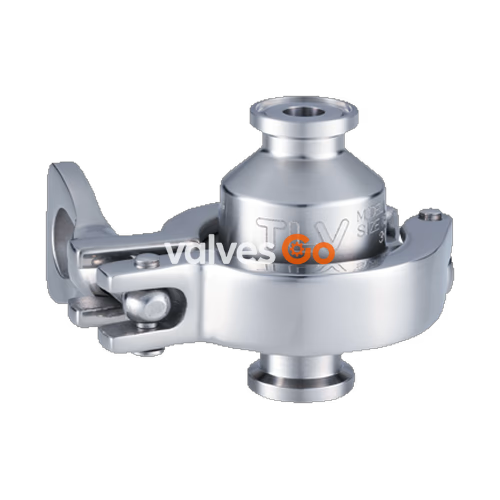
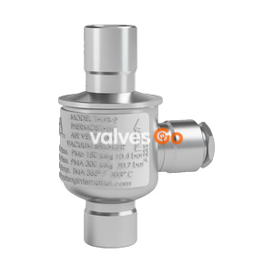
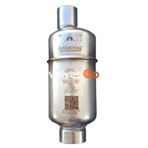
TLV LA6-CE, LA6-SF, LA6-P, and LA6-EP are compact stainless steel thermostatic air vents with a fail-open feature for steam, designed for vertical installation. They are highly recommended for use in pure and clean steam systems.
The product features a revolutionary design utilizing a high-performance X-element. This is a new type of valve mechanism in which a thermoliquid is sealed inside the X-element and the valve opens or closes based on the difference between the saturation temperatures of the thermoliquid and the water. The X-element is very sensitive to changes in temperature and responds with great accuracy, quickly discharging air and the large quantities of condensate created immediately after operation start-up, thereby greatly reducing start-up time. It also reacts with great sensitivity to the hot air accumulated during operation, preventing air-locking.
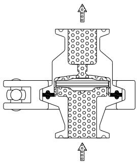
1. Start-up Air and Gas Discharge Initially, the X-element is open and air in piping is quickly vented, significantly shortening equipment start-up time.
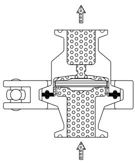
2. Closed Position When an initial air and gas is discharged and steam flows in, the increased temperature causes the X-element to close immediately. If the temperature around the X-element is near steam saturation temperature, the vent will remain closed.
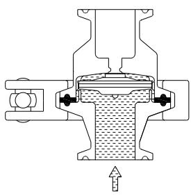
3. Air and Gas Discharge When the temperature of the X-element decreases due to inflowing air, the X-element contracts opening the vent and allowing air discharge.
WARNING
Install properly and DO NOT use this product outside the recommended operating pressure, temperature and other specification ranges. Improper use may result in such hazards as damage to the product or malfunctions that may lead to serious accidents. Local regulations may restrict the use of this product to below the conditions quoted.
| Model | LA6-CE | LA6-SF | LA6-P* |
|---|---|---|---|
| Connection | Clamp End / Tube End | Clamp End / Tube End | Clamp End / Tube End |
| Size | DN 15, 20, 25 / DN 8, 10, 15, 20, 25 | DN 15, 20, 25 / DN 8, 10, 15, 20, 25 | DN 15, 20, 25 / DN 8, 10, 15, 20, 25 |
| Maximum Operating Pressure (barg) PMO | 6 | 6 | 6 |
| Minimum Operating Pressure (barg) | 0.1 | 0.1 | 0.1 |
| Maximum Operating Temperature (°C) TMO | 165 | 165 | 165 |
| Subcooling of X-element Fill (°C) | Up to 22 | Up to 22 | Up to 22 |
| X-element type | Standard | Standard | Electro-polished |
| Clamp Type | 2-Piece Clamp (Buff Polished) | 2-Piece Clamp (Buff Polished) | 3-Piece Clamp (Buff Polished) |
| Finishing (Internal / External) | Natural Machining | 0.8 μm Ra / 1.2 μm Ra Fine Machining | 0.8 μm Ra / 1.2 μm Ra Buff Polished |
*LA6-EP with 0.4 μm Ra electro-polishing available on request.
Pressure Shell Design Conditions (Not Operating Conditions):
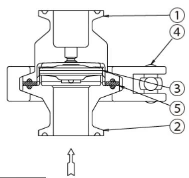
| No. | Description | Material | DIN* | ASTM/AISI* |
|---|---|---|---|---|
| 1 | Upper Body | Stainless Steel AISI316L | 1.4404 | AISI316L |
| 2 | Lower Body | Stainless Steel AISI316L | 1.4404 | AISI316L |
| 3 | X-element | Stainless Steel SUS316L | 1.4404 | AISI316L |
| 4 | Body Clamp | Cast Stainless Steel A351 Gr.CF8 | 1.4312 | A351 Gr.CF8 |
| 5 | Body Gasket** | High-performance Fluorine Resin | - | - |
| 6 | Wing Nut | Stainless Steel | - | - |
*Equivalent materials. **Body gasket is GYLON BIO-PRO; complies with FDA 21 CFR 177.1550, USP Class VI and EC 1935/2004.
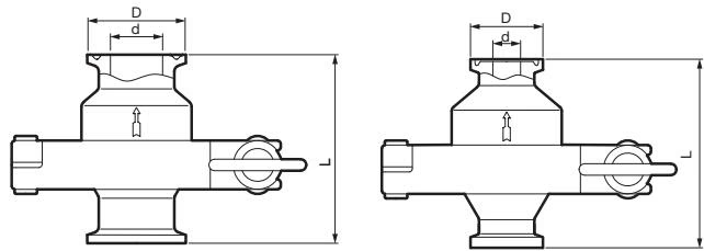
| DN [Size] | L (mm) | φD (mm) | φd (mm) | Weight (kg) |
|---|---|---|---|---|
| 15 [1/2"] | 65 | 34 [25] | 15.2 [9.4] | 0.5 |
| 20 [3/4"] | 65 | 34 [25] | 19.3 [15.75] | 0.55 |
| 25 [1"] | 65 | 50.5 | 22.6 [22.1] | 0.6 |
*ISO 2852 Clamp / ISO 2037 Tube or ASME-BPE (Tri-Clamp compatible). [ ] ASME-BPE (Tri-Clamp compatible).
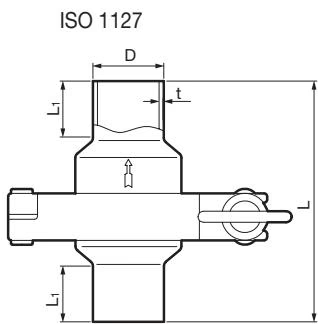
| DN | L (mm) | L1 (mm) | φD (mm) | t (mm) | Weight (kg) |
|---|---|---|---|---|---|
| 8 | 90 | 20 | 13.5 | 1.6 | 0.5 |
| 10 | 90 | 20 | 17.2 | 1.6 | 0.55 |
| 15 | 90 | 20 | 21.3 | 1.6 | 0.55 |
| 20 | 90 | 20 | 26.9 | 1.6 | 0.55 |
| 25 | 90 | 20 | 33.7 | 2.0 | 0.6 |
*ISO 1127, other standards available.
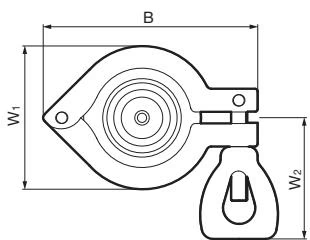
| DN | 2-Piece: LA6-CE / LA6-SF (B / W1 / W2) | 3-Piece: LA6-P (B / W1 / W2) |
|---|---|---|
| 8, 10, 15, 20, 25 | 92 / 62 / 55 mm | 82 / 70 / 55 mm |
WARNING
Take measures to prevent people from coming into direct contact with product outlets. Failure to do so may result in burns or other injury from the discharge of fluids.
WARNING
When disassembling or removing the product, wait until the internal pressure equals atmospheric pressure and the surface of the product has cooled to room temperature. Disassembling or removing the product when it is hot or under pressure may lead to discharge of fluids, causing burns, other injuries or damage.
| Problem | Cause | Remedy |
|---|---|---|
| No air or gas is discharged (blocked) or discharge is poor | The X-element is stuck to the valve seat | Clean parts |
| The valve seat is blocked | Clean the valve seat, or replace with a new valve seat or cover | |
| The screen is clogged | Clean parts | |
| The air vent operating pressure exceeds the maximum specified pressure, or there is insufficient pressure differential | Compare specifications and actual operating conditions | |
| Steam is discharged or leaks from the outlet (blowing/steam leakage) | There is rust or scale between the X-element valve and valve seat | Clean parts |
| The X-element valve and valve seat are damaged | Replace with a new X-element and/or cover | |
| The X-element is broken | Replace with a new X-element | |
| Improper installation | Correct the installation | |
| Product vibration | Lengthen the inlet piping and fasten it securely | |
| Steam is leaking from a place other than the outlet | Gasket deterioration or damage | Replace with a new gasket |
| Improper tightening torques were used | Tighten to the proper torque (Wing Nut: 8.0 N·m) |
Explore similar products in our catalog