All-Stainless Steel Material

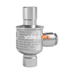
TLV VS1C-M2 stainless steel automatic air vent for vertical installation in high temperature liquid systems. Features a precision-ground float, 21 barg maximum allowable pressure, and dual function as an air vent and vacuum breaker.
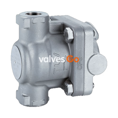
TLV VS1C-M2 is a stainless steel automatic air vent designed for vertical installation in high-temperature liquid systems. It automatically vents air from liquids with a specific gravity above 0.8, which ensures quick system start-up and efficient water transport. The air vent also automatically discharges air that is entrained in the water during operation and has collected in specific locations in the piping. In addition to venting air, it serves a dual function as a vacuum breaker.

WARNING
DO NOT use for toxic, flammable or otherwise hazardous fluids. This product is an air vent that discharges air from water piping systems. Use only for water and/or air.
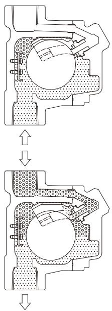
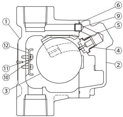
| No. | Description | Material | DIN | ASTM/AISI |
|---|---|---|---|---|
| 1 | Body | Cast Stainless Steel | 1.4312 | A351/A351M Gr.CF8 |
| 2 | Cover | Cast Stainless Steel | 1.4312 | A351/A351M Gr.CF8 |
| 3 | Float | Stainless Steel | 1.4404 | AISI316L |
| 4 | Valve Seat | Fluorine Rubber / Stainless Steel | FPM/1.4305 | D2000HK/AISI303 |
| 5 | Valve Seat Gasket | Fluorine Resin PTFE | - | - |
| 6 | Cover Gasket | Fluorine Resin PTFE | - | - |
| 7 | Cover Bolt | Stainless Steel | - | - |
| 8 | Nameplate | Stainless Steel | 1.4301 | AISI304 |
| 9 | Connector | Stainless Steel | 1.4301 | AISI304 |
| 10 | Screw | Stainless Steel | 1.4301 | AISI304 |
| 11 | Spring Washer | Stainless Steel | 1.4301 | AISI304 |
| 12 | Guide Plate | Stainless Steel | 1.4301 | AISI304 |
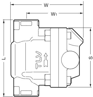
| Size | L (mm) | W (mm) | W1 (mm) | S (mm) | Weight (kg) |
|---|---|---|---|---|---|
| 15 | 110 | 110 | 85 | 85 | 1.5 |
| 20 | 120 | 110 | 85 | 85 | 1.5 |
| 25 | 130 | 110 | 85 | 85 | 1.7 |
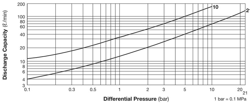
INFO
| Problem | Cause | Remedy |
|---|---|---|
| No air is discharged (blocked) or discharge is poor | The trapped air cannot displace the water in the piping | Correct the inlet piping (Inner diameter should be at least 16 mm) |
| The valve seat is clogged with dirt or foreign matter | Clean the valve seat | |
| The inlet or outlet piping is clogged | Clean the piping | |
| Operating pressure exceeds the rated maximum | Replace with a product of suitable operating pressure | |
| Water leaks when the valve is closed | Build-up of rust/scale on the valve seat, or seat is damaged | Clean or replace with a new valve seat |
| Float is misshapen, dirty or has a film build-up | Clean or replace with a new float | |
| Improper installation orientation | Correct the installation | |
| Vent does not close and water is blowing | Float is damaged or filled with water | Replace with a new float |
| Specific gravity of the liquid is not suitable | Select a product with suitable specifications |
Explore similar products in our catalog