Stainless Steel

TLV NF6 brass automatic non-freeze drain valve for free float steam traps. Features 2.0 MPaG max operating pressure, 220 °C max temperature, and built-in screen.
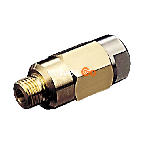
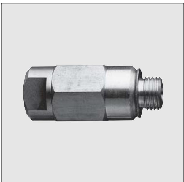
The TLV NF6 is a compact, brass automatic non-freeze valve designed as a drain option for free float steam traps. It reliably drains residual condensate from traps provided with drain plugs to prevent freeze-up in cold areas. The valve opens automatically to drain residual condensate shortly after the shut-off of steam-using equipment when steam pressure in the trap decreases to approximately 0.2 barg (0.02 MPaG). It closes steam-tight immediately after startup when the pressure rises to about 0.3 barg (0.03 MPaG). The normal operation of the steam trap is unaffected by the NF6, and its built-in screen protects the valve from clogging.
| Model | NF6 |
|---|---|
| Connection | Screwed |
| Size | 1/4" |
| Maximum Operating Pressure (PMO) | 2.0 MPaG (20 barg) |
| Maximum Operating Temperature (TMO) | 220 °C |
| Valve Opening Pressure | approx. 0.02 MPaG (0.2 barg) |
| Valve Closing Pressure | approx. 0.03 MPaG (0.3 barg) |
Pressure Shell Design Conditions (Not Operating Conditions):
WARNING
Install properly and DO NOT use this product outside the recommended operating pressure, temperature and other specification ranges. Improper use may result in such hazards as damage to the product or malfunctions which may lead to serious accidents. Local regulations may restrict the use of this product to below the conditions quoted.
INFO
When used in extreme cold, due to the possibility of freezing while discharging, prevention of freezing cannot be guaranteed.
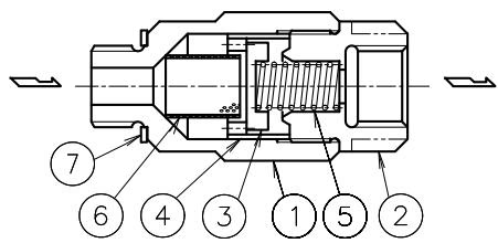
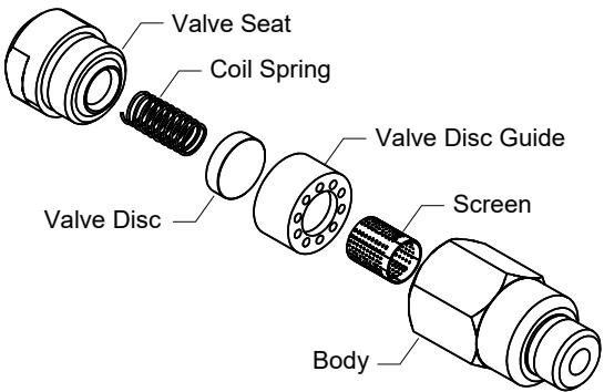
| No. | Description | Material | DIN* | ASTM/AISI* |
|---|---|---|---|---|
| 1 | Body | Brass C3604 | 2.0401 | B16 C36000 |
| 2 | Valve Seat | Stainless Steel SUS303 | 1.4305 | AISI303 |
| 3 | Valve Disc | Stainless Steel SUS303 | 1.4305 | AISI303 |
| 4 | Valve Disc Guide | Brass C3601 | 2.0375 | B16 C36000 |
| 5 | Coil Spring | Stainless Steel SUS304 | 1.4301 | AISI304 |
| 6 | Screen | Stainless Steel SUS304 | 1.4301 | AISI304 |
| 7 | Gasket** | Copper C1100P | - | B152 |
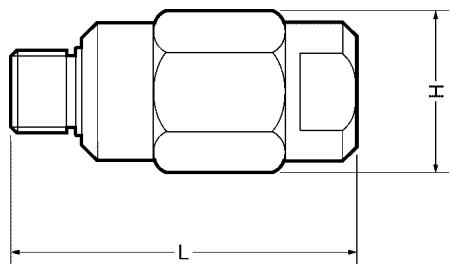
| Size | L (mm) | H (mm) | Weight (kg) |
|---|---|---|---|
| 1/4" | 51 | 24 | 0.1 |
Inlet: G(PF) 1/4 male or R(PT) 1/4, Outlet: G(PF) 1/4 female. Other standards available.
WARNING
Take measures to prevent people from coming into direct contact with product outlets. Failure to do so may result in burns or other injury from the discharge of fluids.
WARNING
Do not use excessive force when connecting threaded pipes to the product. Over-tightening may cause breakage leading to fluid discharge, which may cause burns or other injury.
1. Outlet pipe should have as steep a downward incline as possible Condensate needs to be discharged from the piping before the temperature decreases below the freezing point. This product cannot function once freezing has occurred at the outlet side. Do not recover the condensate.
2. Outlet piping should be as thick and as short as possible Freezing occurs from the outside of the outlet pipe. If the outlet pipe is thin and long, the condensate temperature can decrease while flowing, gradually freezing along the pipe's inner surface. Eventually, the pipe may become blocked, with condensate backing up and freezing in the steam trap, possibly causing damage. To prevent such an occurrence, the outlet pipe should be as thick and as short as possible with an internal diameter ø6 mm (15/64") or larger and discharge to atmosphere.
3. Relation between required inlet pressure and length of NF6 outlet pipe If there are any bends, or the pipe length is long, outlet pressure of NF6 increases due to high resistance from the pipe, and the valve may not close. To avoid such a phenomenon, use the non-freeze valve on a steam trap with an inlet pressure shown on the following graph.
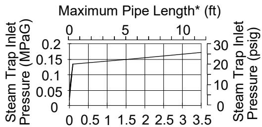
Use the non-freeze valve on a steam trap with an inlet pressure as shown on the graph. ø6 mm (15/64") or larger internal diameter and bending at no more than 3 locations.
WARNING
When disassembling or removing the product, wait until the internal pressure equals atmospheric pressure and the surface of the product has cooled to room temperature. Disassembling or removing the product when it is hot or under pressure may lead to discharge of fluids, causing burns, other injuries or damage.
| Part | Procedure |
|---|---|
| Valve Disc & Valve Seat | Check for oil film, warping, scratches or other wear |
| Screen | Check for clogging or corrosion |
| Part | Torque N·m (lbf·ft) | Distance Across Flats mm (in) |
|---|---|---|
| Valve Seat* | 35 (26) | 17 (21/32) |
| Body (Straight G(PF) thread)* | 35 (26) | 21 (13/16) |
| Body (Tapered R(PT) thread) | 30 (22) | 21 (13/16) |
*Coat threads with anti-seize.
| Problem | Cause | Remedy |
|---|---|---|
| No condensate is discharged (blocked) or discharge is poor | Valve disc, valve seat, screen, or piping is clogged with rust or scale | Clean parts |
| Freezing occurs on outlet pipe, etc. | Examine the size, length and installation of the outlet pipe and take appropriate corrective measures | |
| Steam is discharged or leaks from the outlet (blowing) (steam leakage) | Rust or scale or other build up have accumulated on the valve disc or valve seat | Clean parts |
| Valve disc or valve seat are damaged | Replace with a new valve and valve seat | |
| Improper installation orientation | Reinstall with correct flow direction | |
| Improper installation, size or length of outlet pipe | Make sure outlet pipe is at least ø6 mm (15/64") internal dia., of appropriate length and has no more than 3 bends | |
| Steam leaks from a place other than the outlet | Gasket deterioration or damage | Replace with a new gasket |
| Improper tightening torques were used | Tighten to the proper torque |
Explore similar products in our catalog