All-Stainless Steel Material

TLV VS3 series sanitary automatic air vents for liquid systems. Stainless steel, float-type mechanical valve for pharmaceutical and biotech industries.
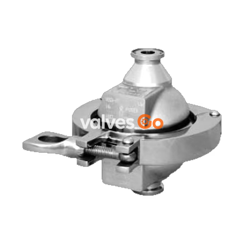
TLV VS3 series automatic air vents (clean air vents) are designed to automatically discharge and release air trapped in water-carrying pipes during water transport. It also automatically discharges the air that was entrained in the water during operation and has subsequently been separated and collected in specific locations in the piping.
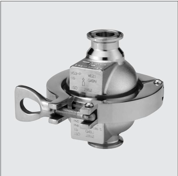
These float-type mechanical valves are recommended for venting air in purified water and other liquid systems such as in the pharmaceutical, biotechnology, and cosmetics industries.
When water starts to flow through the piping, air trapped within the piping is pushed along by the water pressure and enters the air vent. At first, because the float is positioned in the lower part of the air vent, the valve is fully open and the air passes through the valve seat and is discharged rapidly through the vent. 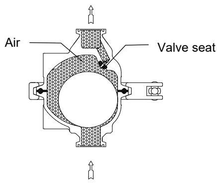
When the air has been discharged and water begins to enter the air vent, the float starts to rise due to buoyancy. This pushes it upwards against the valve opening, thus closing the air vent. If there is a rapid rise in water level (caused by rapidly opening a shut-off valve, etc.), a small amount of water may leak with discharged air immediately before the air vent closes. 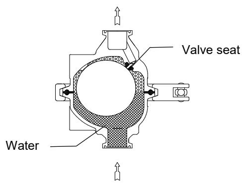
When more air is trapped in the air vent due to the inflow of water having closed the valve, the water level in the air vent is forced down and consequently the level of the float falls, opening the valve. Air can now again escape through the air vent, and as it does so the level of the water rises, pushing the float upwards again to close the valve. In this way the VS3 series automatically adjusting air vents constantly respond to the flow of air.
When draining the piping, the air vent automatically opens to introduce air and remove water more easily (preventing a vacuum from forming in the piping). 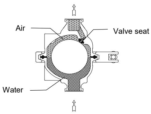
WARNING
DO NOT use for toxic, flammable or otherwise hazardous fluids. Use only for water and/or air.
| Model | VS3-E | VS3-P | VS3-EP |
|---|---|---|---|
| Connection | Clamp End | Clamp End | Clamp End |
| Size | DN 15, 20 (ISO) 3/4" (ASME-BPE) | DN 15, 20 (ISO) 3/4" (ASME-BPE) | DN 15, 20 (ISO) 3/4" (ASME-BPE) |
| Maximum Operating Pressure (barg) PMO | 6 | 6 | 6 |
| Maximum Differential Pressure (bar) ΔPMX | 6 | 6 | 6 |
| Maximum Operating Temperature (°C) TMO | 150 | 150 | 150 |
| Clamp type | 3-piece (buff-polished) | 3-piece (buff-polished) | 3-piece (buff-polished) |
| Finishing Internal | 25 μm Ra electro-polished | 0.8 μm Ra buff-polished | Buff-polished then 0.4 μm Ra electro-polished |
| Finishing External | 25 μm Ra electro-polished | 0.8 μm Ra buff-polished | Buff-polished then 0.4 μm Ra electro-polished |
| Applicable Fluid | Water, Other Liquids (Specific gravity must be at least 0.8) | Water, Other Liquids (Specific gravity must be at least 0.8) | Water, Other Liquids (Specific gravity must be at least 0.8) |
Pressure Shell Design Conditions: Maximum Allowable Pressure (PMA): 10 barg. Maximum Allowable Temperature (TMA): 185 °C.
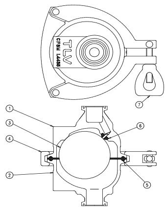
| No. | Description | Material |
|---|---|---|
| 1 | Body | Cast Stainless Steel A351 Gr.CF3M |
| 2 | Cover | Cast Stainless Steel A351 Gr.CF3M |
| 3 | Float | Stainless Steel SUS316L |
| 4 | Body Clamp | Cast Stainless Steel A351 Gr.CF8 |
| 5 | Cover Gasket | High-performance Fluorine Resin |
| 6 | Valve Seat | Silicone Rubber |
WARNING
Install properly and DO NOT use this product outside the recommended operating pressure, temperature and other specification ranges.
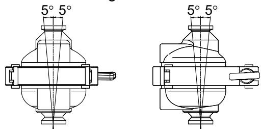
Make sure the product is installed with the raised TLV lettering on the body horizontal.
VS3-P Clamp End (ISO 2852 Clamp / ISO 2037 Tube or ASME-BPE Tri-Clamp compatible)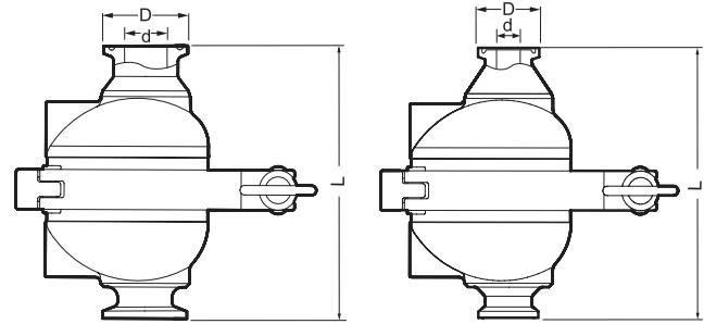
| DN | L (mm) | W (mm) | B (mm) | φD (mm) | φd (mm) | Weight (kg) |
|---|---|---|---|---|---|---|
| 15 | 105 | 105 | 125 | 34 | 15.2 | 1.4 |
| 20 (3/4") | 105 | 105 | 125 | 34 (25) | 19.3 (15.75) | 1.4 (1.3) |
Explore similar products in our catalog