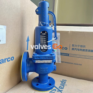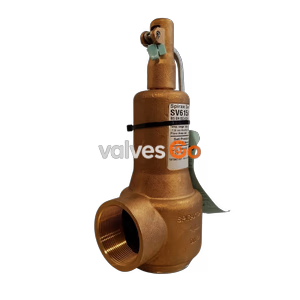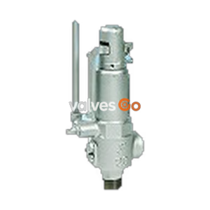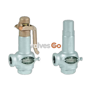
Lift Type

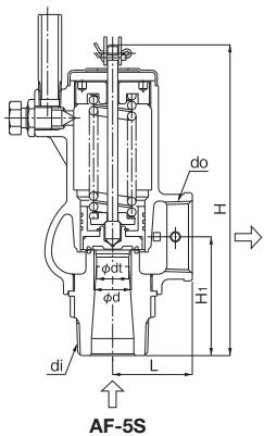
Yoshitake AF-5 full bore safety valve (0.1-2.0 MPa) and AF-5S stainless steel model (0.1-1.0 MPa). Compact and lightweight for steam, air, and non-dangerous fluids.
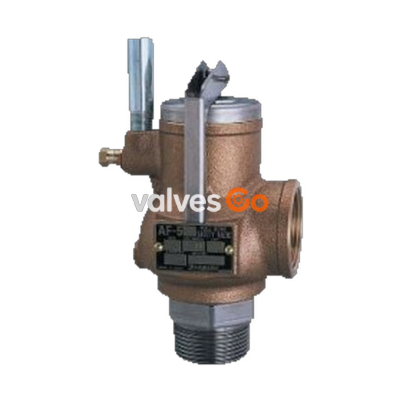
Yoshitake AF-5 is a full bore safety valve designed with increased safety. It is compact and lightweight, approximately half the size of previous full bore type safety valves. The AF-5 features trim parts made of excellent quality materials, maintaining high performance through precision processing and heat treatment.
It incorporates a lift lever mechanism that allows a discharge inspection to be manually performed at more than 75% of the opening pressure. The related AF-5S model features an all-stainless steel construction for high corrosion resistance and durability.
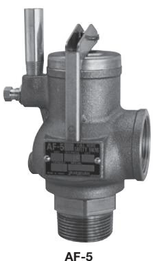
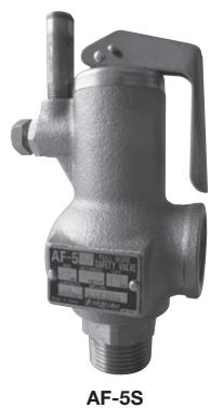
| Model | AF-5 | AF-5S |
|---|---|---|
| Structure | Open type with a lever | Open type with a lever |
| Application | Steam | Steam, Air, Other non-dangerous fluids |
| Working pressure | 0.1-2.0 MPa | 0.1-1.0 MPa |
| Maximum temperature | 220°C | 220°C |
| Material (Spring case) | Bronze | Stainless steel |
| Material (Valve, valve seat) | Stainless steel | Stainless steel |
| Connection | Inlet: JIS R screwed Outlet: JIS Rc screwed | Inlet: JIS R screwed Outlet: JIS Rc screwed |
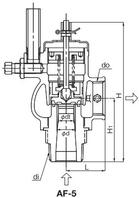
| Nominal size | Inlet diameter x Throat diameter x Outlet diameter (di x dt x do) | Valve seat diameter | Flow area $\frac{\pi}{4}dt^{2}(mm^{2})$ | Lift ℓ (mm) | Dimension L (mm) | Dimension $H_1$ (mm) | Dimension H (mm) | Plug | Weight (kg) |
|---|---|---|---|---|---|---|---|---|---|
| 20A | R 1 x 15 x Rc 1 | 18 | 176.6 | 3.3 | 38 | 61 | 136 (151) | R 1/8 | 1.3 (1.5) |
| 25A | R 1-1/4 x 19 x Rc 1-1/4 | 22 | 283.3 | 4.4 | 45 | 70 | 157 (182) | R 1/8 | 1.9 (2.1) |
| 32A | R 1-1/2 x 24 x Rc 1-1/2 | 28 | 452.1 | 5.5 | 52 | 80 | 183 (202) | R 1/8 | 2.7 (3.0) |
| 40A | R 2 x 30 x Rc 2 | 35 | 706.5 | 6.8 | 65 | 98 | 216 (252) | R 1/4 | 5.1 (6.0) |
| 50A | R 2-1/2 x 38 x Rc 2-1/2 | 44 | 1133.5 | 8.7 | 77 | 121 | 262 (314) | R 1/4 | 8.4 (9.5) |
| Nominal size | Inlet diameter x Throat diameter x Outlet diameter (di x dt x do) | Valve seat diameter | Flow area $\frac{\pi}{4}dt^{2}(mm^{2})$ | Lift ℓ (mm) | Dimension L (mm) | Dimension $H_1$ (mm) | Dimension H (mm) | Plug | Weight (kg) |
|---|---|---|---|---|---|---|---|---|---|
| 20A | R 1 x 15 x Rc 1 | 18 | 176.6 | 3.3 | 40 | 62 | 163 | R 1/8 | 1.65 |
| 25A | R 1-1/4 x 19 x Rc 1-1/4 | 22 | 283.3 | 4.4 | 47 | 70 | 190 | R 1/8 | 2.35 |
| 32A | R 1-1/2 x 24 x Rc 1-1/2 | 28 | 452.1 | 5.5 | 52 | 79 | 208 | R 1/8 | 2.90 |
| 40A | R 2 x 30 x Rc 2 | 35 | 706.5 | 6.8 | 65 | 98 | 248 | R 1/4 | 5.30 |
| 50A | R 2-1/2 x 38 x Rc 2-1/2 | 44 | 1133.5 | 8.7 | 77 | 121 | 315 | R 1/4 | 9.20 |
| Nominal size \ Pressure MPa | 0.1 | 0.2 | 0.3 | 0.4 | 0.5 | 0.6 | 0.7 | 0.8 | 0.9 | 1.0 | 1.1 | 1.2 | 1.3 | 1.4 | 1.5 | 1.6 | 1.7 | 1.8 | 1.9 | 2.0 | |---|---|---|---|---|---|---|---|---|---|---|---|---|---|---|---|---|---|---|---| | 20A | 159 | 231 | 310 | 390 | 468 | 545 | 621 | 697 | 773 | 849 | 925 | 1001 | 1076 | 1152 | 1227 | 1303 | 1378 | 1455 | 1531 | 1606 | | 25A | 255 | 370 | 498 | 627 | 751 | 875 | 997 | 1118 | 1240 | 1362 | 1484 | 1606 | 1726 | 1849 | 1968 | 2090 | 2211 | 2335 | 2456 | 2576 | | 32A | 407 | 591 | 794 | 1000 | 1199 | 1396 | 1591 | 1785 | 1979 | 2175 | 2369 | 2562 | 2755 | 2950 | 3142 | 3336 | 3529 | 3726 | 3919 | 4112 | | 40A | 636 | 925 | 1242 | 1563 | 1874 | 2182 | 2487 | 2790 | 3093 | 3398 | 3702 | 4005 | 4306 | 4611 | 4910 | 5213 | 5515 | 5823 | 6125 | 6425 | | 50A | 1021 | 1484 | 1992 | 2508 | 3007 | 3501 | 3991 | 4477 | 4963 | 5453 | 5940 | 6425 | 6909 | 7398 | 7877 | 8364 | 8849 | 9343 | 9826 | 10309 |
| Nominal size \ Pressure MPa | 0.1 | 0.2 | 0.3 | 0.4 | 0.5 | 0.6 | 0.7 | 0.8 | 0.9 | 1.0 | 1.1 | 1.2 | 1.3 | 1.4 | 1.5 | 1.6 | 1.7 | 1.8 | 1.9 | 2.0 | |---|---|---|---|---|---|---|---|---|---|---|---|---|---|---|---|---|---|---|---| | 20A | 155 | 227 | 299 | 372 | 443 | 515 | 587 | 659 | 729 | 800 | 872 | 942 | 1013 | 1084 | 1156 | 1227 | 1296 | 1367 | 1439 | 1510 | | 25A | 249 | 365 | 480 | 598 | 711 | 827 | 942 | 1057 | 1170 | 1284 | 1398 | 1512 | 1625 | 1740 | 1854 | 1968 | 2080 | 2193 | 2309 | 2422 | | 32A | 398 | 582 | 767 | 954 | 1136 | 1320 | 1503 | 1687 | 1867 | 2050 | 2232 | 2413 | 2594 | 2777 | 2959 | 3141 | 3319 | 3500 | 3685 | 3865 | | 40A | 622 | 910 | 1198 | 1491 | 1775 | 2063 | 2350 | 2636 | 2918 | 3204 | 3488 | 3772 | 4054 | 4340 | 4625 | 4909 | 5187 | 5470 | 5759 | 6041 | | 50A | 998 | 1461 | 1923 | 2393 | 2848 | 3311 | 3770 | 4229 | 4681 | 5140 | 5597 | 6052 | 6505 | 6963 | 7420 | 7876 | 8323 | 8777 | 9239 | 9692 |
| Nominal size \ Pressure MPa | 0.1 | 0.2 | 0.3 | 0.4 | 0.5 | 0.6 | 0.7 | 0.8 | 0.9 | 1.0 |
|---|---|---|---|---|---|---|---|---|---|---|
| 20A | 257 | 374 | 502 | 630 | 759 | 887 | 1015 | 1143 | 1272 | 1400 |
| 25A | 413 | 600 | 806 | 1011 | 1217 | 1423 | 1629 | 1835 | 2040 | 2246 |
| 32A | 659 | 958 | 1286 | 1614 | 1943 | 2271 | 2600 | 2928 | 3256 | 3585 |
| 40A | 1030 | 1497 | 2010 | 2523 | 3036 | 3550 | 4063 | 4576 | 5089 | 5602 |
| 50A | 1654 | 2402 | 3225 | 4049 | 4872 | 5695 | 6518 | 7342 | 8165 | 8988 |
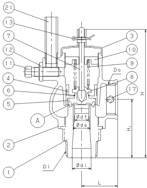
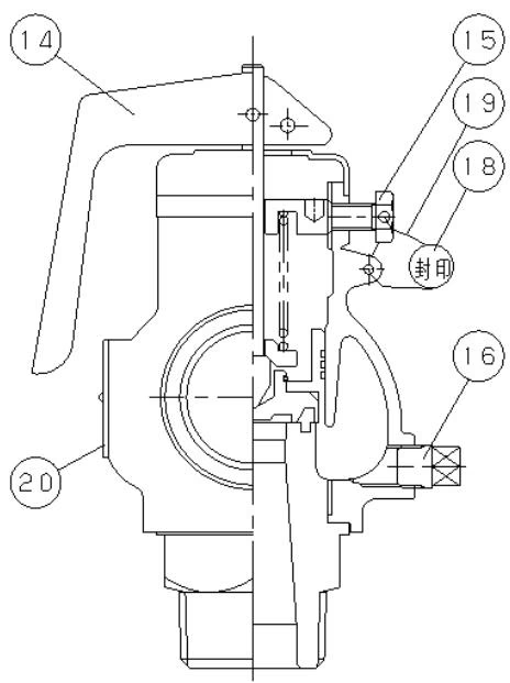
| No. | Part Name | No. | Part Name | No. | Part Name |
|---|---|---|---|---|---|
| 1 | Valve seat | 8 | Spring plate | 15 | Hexagon bolt |
| 2 | Spring chamber | 9 | Spring | 16 | Plug |
| 3 | Cover | 10 | Adjusting screw | 17 | Hexagon bolt |
| 4 | Valve guide | 11 | Needle valve | 18 | Seal ball |
| 5 | Valve | 12 | Lock nut | 19 | Seal wire |
| 6 | Retaining Ring C type | 13 | Split pin | 20 | Nameplate |
| 7 | Spindle | 14 | Lever | 21 | Pipe |
(1) Blowout operation As inlet pressure approaches the blowout pressure, the force of fluid pushing up the valve approaches the force of the spring pressing down the valve. The safety valve commences to blow when the inlet pressure reaches around 3% below the blowout pressure. The fluid starts to leak by simmering and accumulates gradually on the valve holder A. When the fluid pressure reaches the blowout pressure the valve pops.
(2) Closing operation Since the inlet pressure of the safety valve decreases when the fluid is released into the atmosphere by the pop action of the valve, the force of fluid lift is lowered. At this point, the repelling force of the spring becomes larger than the force of fluid lift and thus the valve closes. In addition, since the safety valve blows, the pressure of fluid entering into the back of the valve holder (back pressure) adds to the closing force.
(3) Lift lever mechanism
WARNING
Due to lift lever mechanism a discharge inspection can be manually performed at more than 75% of the blowout pressure.
Yoshitake Safety Valves / Relief Valves
AF and AL series safety and relief valves for overpressure protection of steam, water, and air equipment.
Explore similar products in our catalog