Lift Type

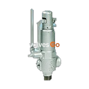
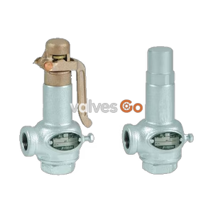
Yoshitake AL-250R stainless steel closed type relief valve with handle. Features a dash-pot structure to prevent chattering and hunting. For water, oil, and non-dangerous fluids.
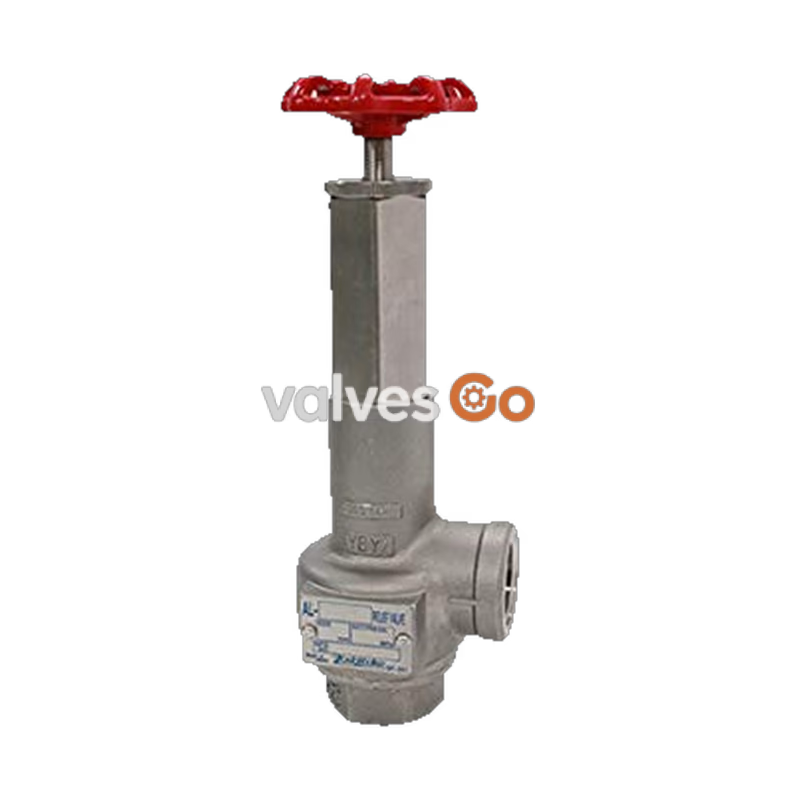
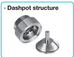
Yoshitake AL-250R is a closed type relief valve made of stainless steel, equipped with a handle for easy pressure adjustment. It is designed to regulate pulsating and fluctuating pressure for large capacity pumps, offering high corrosion resistance and durability. The unique dash-pot structure is remarkably effective for lines with heavy pulsation, preventing chattering and hunting while maintaining stable operation against back pressure changes produced in continuous blow.
| Model | AL-250 | AL-250R |
|---|---|---|
| Structure | Closed type | Closed type with a handle |
| Application | Cold and hot water, Oil, Other non-dangerous fluids (Less than 20 cSt) | Cold and hot water, Oil, Other non-dangerous fluids (Less than 20 cSt) |
| Working pressure | 0.05-1.0 MPa | 0.05-1.0 MPa |
| Maximum temperature | 120°C | 90°C |
| Spring case material | Cast stainless steel | Cast stainless steel |
| Valve, valve seat material | Stainless steel | Stainless steel |
| Connection | JIS Rc screwed | JIS Rc screwed |
| Nominal size | 15-50A | 15-50A |
WARNING
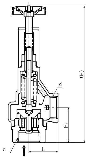
| Nominal size | d | L (mm) | $H_1$ (mm) | H (mm) | Weight (kg) |
|---|---|---|---|---|---|
| 15A | Rc 1/2 | 34 | 41.0 | 185 | 0.9 |
| 20A | Rc 3/4 | 38 | 45.0 | 190 | 1.1 |
| 25A | Rc 1 | 43 | 51.5 | 205 | 1.4 |
| 32A | Rc 1-1/4 | 50 | 63.5 | 245 | 2.5 |
| 40A | Rc 1-1/2 | 60 | 68.5 | 280 | 3.7 |
| 50A | Rc 2 | 75 | 80.0 | 315 | 6.0 |
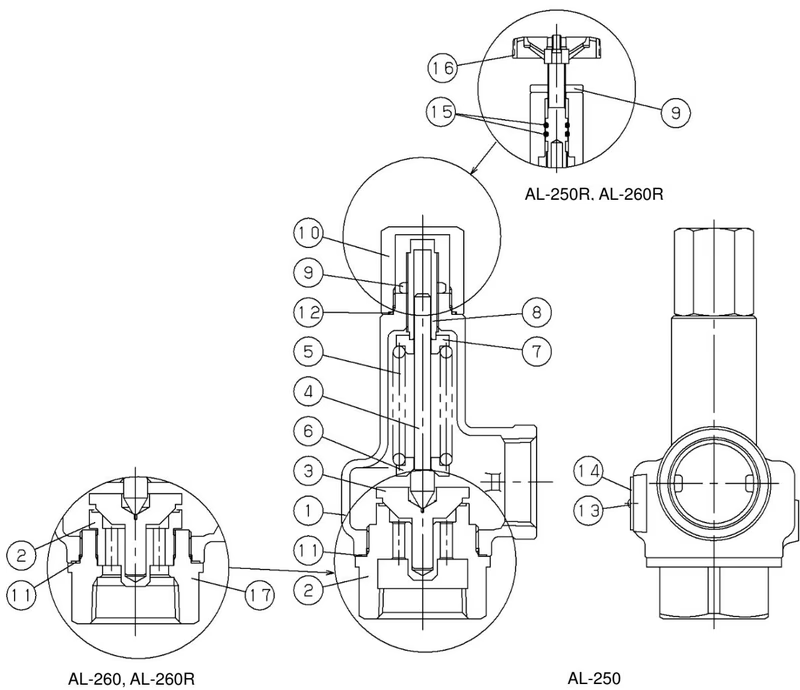
| No. | Part name | No. | Part name | No. | Part name |
|---|---|---|---|---|---|
| 1 | Spring case | 7 | Top spring plate | 13 | Rivet |
| 2 | Valve seat | 8 | Adjusting screw | 14 | Name plate |
| 3 | Valve | 9 | Lock nut | 15 | O ring |
| 4 | Spindle | 10 | Cap | 16 | Handle |
| 5 | Spring | 11 | Gasket | 17 | Valve Case |
| 6 | Bottom spring plate | 12 | Gasket |
When the pressure of the inlet side of the relief valve increases and approaches the blowout pressure, the force of liquid pressure pushes the valve upward and approaches the force of the spring which pushes down the valve, and the valve is opened after increasing more pressure, then the fluid is released. The pressure is controlled by changing the degree of valve depending on the inlet pressure.
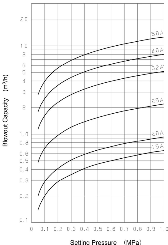
Discharge capacity (accumulation: 25%) (m³/h)
| Nominal size | 0.05 MPa | 0.1 MPa | 0.2 MPa | 0.3 MPa | 0.4 MPa | 0.5 MPa | 0.6 MPa | 0.7 MPa | 0.8 MPa | 0.9 MPa | 1.0 MPa |
|---|---|---|---|---|---|---|---|---|---|---|---|
| 15A | 0.14 | 0.20 | 0.29 | 0.35 | 0.41 | 0.46 | 0.50 | 0.54 | 0.58 | 0.62 | 0.65 |
| 20A | 0.20 | 0.29 | 0.41 | 0.51 | 0.59 | 0.66 | 0.72 | 0.78 | 0.83 | 0.88 | 0.93 |
| 25A | 0.49 | 0.69 | 0.98 | 1.20 | 1.38 | 1.54 | 1.69 | 1.83 | 1.96 | 2.07 | 2.19 |
| 32A | 1.14 | 1.62 | 2.29 | 2.81 | 3.24 | 3.63 | 3.97 | 4.29 | 4.59 | 4.87 | 5.13 |
| 40A | 1.79 | 2.53 | 3.58 | 4.39 | 5.07 | 5.67 | 6.21 | 6.71 | 7.17 | 7.61 | 8.02 |
| 50A | 2.80 | 3.96 | 5.60 | 6.86 | 7.92 | 8.86 | 9.71 | 10.49 | 11.21 | 11.89 | 12.53 |
WARNING
Piping Instructions
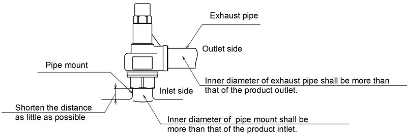
Check the following items while the system is in operation (daily) and regularly (once per 6 months):
| Trouble | Cause | Remedy |
|---|---|---|
| Blows at a pressure lower than the set pressure. | 1. The product specifications are not consistent with the use condition. 2. The pressure gauge is out of order. 3. Foreign substance or scale stuck on contact surface. 4. Damage on the contact surface. 5. The product does not keep the accuracy of its set pressure. | 1. Check set pressure indication. Replace if not suitable. 2. Calibrate or replace pressure gauge. 3. Operate product and eliminate substance. 4. Disassemble and replace parts. 5. Readjust set pressure. |
| Does not operate at the set pressure. | 1. Specifications not consistent with condition. 2. Product does not keep accuracy of set pressure. 3. Pressure gauge is out of order. 4. Sliding parts do not move smoothly. 5. Back pressure at the piping of outlet. | 1. Check set pressure indication. 2. Readjust set pressure. 3. Calibrate or replace pressure gauge. 4. Disassemble and clean. 5. Remove back pressure. |
WARNING
To adjust the set pressure, turn the handle slowly at the rotation of 1/4-1/3 and confirm the operation each time. Be careful of sudden blowout when turned too much. Step away immediately in case of blowout. Be sure to wear gloves while operating the handle of AL-250R.
Procedure for AL-250R:
Set pressure range (MPa) per Spring:
| Nominal size | A | B | C | D | E | F |
|---|---|---|---|---|---|---|
| 15A | 0.05~0.2 | 0.21~0.4 | 0.41~0.55 | 0.56~0.75 | 0.76~1.0 | ——— |
| 20A | 0.05~0.2 | 0.21~0.35 | 0.36~0.45 | 0.46~0.6 | 0.61~0.75 | 0.76~1.0 |
| 25A | 0.05~0.2 | 0.21~0.35 | 0.36~0.45 | 0.46~0.55 | 0.56~0.8 | 0.81~1.0 |
| 32A | 0.05~0.2 | 0.21~0.4 | 0.41~0.65 | 0.66~1.0 | ——— | ——— |
| 40A | 0.05~0.2 | 0.21~0.4 | 0.41~0.65 | 0.66~0.8 | 0.81~1.0 | ——— |
| 50A | 0.05~0.2 | 0.21~0.4 | 0.41~0.65 | 0.66~0.8 | 0.81~1.0 | ——— |
Yoshitake Safety Valves / Relief Valves
AF and AL series safety and relief valves for overpressure protection of steam, water, and air equipment.
Explore similar products in our catalog