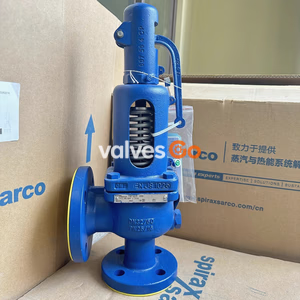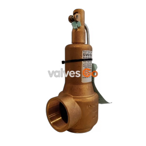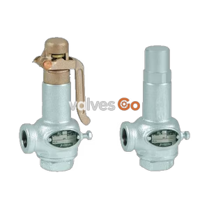
Lift Type

Yoshitake AL-300T and AL-301T lift type safety relief valves for air, water, and oil. Features ductile cast iron body, PTFE disc for excellent airtightness, and 150°C max temperature.
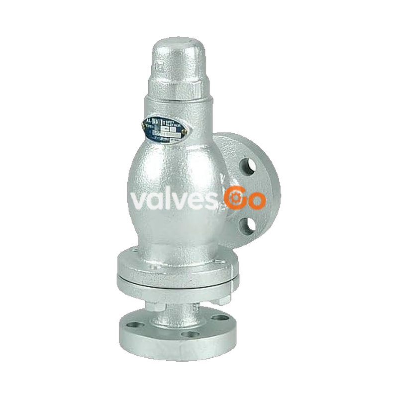
Yoshitake AL-300T and AL-301T are closed-type, lift safety relief valves designed for air, cold and hot water, oil, and other non-dangerous fluids. The valves feature a simple structure that is easy to maintain and adjust. The inclusion of a polytetrafluoroethylene (PTFE) disc between the valve and valve seat ensures excellent airtightness and completely prevents leakage.
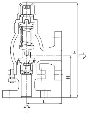
| Model | AL-300T | AL-301T |
|---|---|---|
| Structure | Closed type | Closed type |
| Application | Air, Cold and hot water, Oil, Other non-dangerous fluids | Air, Cold and hot water, Oil, Other non-dangerous fluids |
| Working pressure | 0.05-1.0 MPa | 0.05-1.3 MPa *1 |
| Maximum temperature | 150°C | 150°C |
| Material (Valve case, spring case) | Ductile cast iron | Ductile cast iron |
| Material (Valve, valve seat) | Cast bronze and PTFE | Stainless steel and PTFE |
| Connection | JIS 10K FF flanged *3 | JIS 10K FF flanged *3 |
INFO
*1: Please contact us if working pressure is between 1.31 MPa and 1.6 MPa. *3: JIS 16K FF flanged when working pressure is more than 1.0 MPa.
| Nominal size | L (mm) | H (mm) | H1 (mm) | d (mm) | Flow area (mm²) | Weight (kg) |
|---|---|---|---|---|---|---|
| 15A | 90 | 245 | 108 | 29 | 66.1 | 4.7 |
| 20A | 90 | 245 | 108 | 29 | 66.1 | 5.0 |
| 25A | 90 | 245 | 108 | 29 | 66.1 | 6.2 |
| 32A | 91 | 285 | 115 | 37 | 107.6 | 8.6 |
| 40A | 91 | 285 | 115 | 37 | 107.6 | 8.8 |
| 50A | 105 | 311 | 132 | 50 | 196.4 | 12.6 |
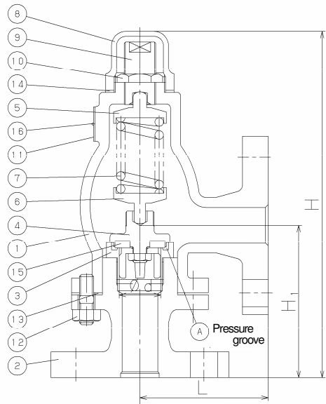
| No. | Part name | No. | Part name |
|---|---|---|---|
| 1 | Spring case | 9 | Adjusting screw |
| 2 | Valve case | 10 | Lock nut |
| 3 | Valve seat | 11 | Name plate |
| 4 | Valve | 12 | Stud bolt & nut |
| 5 | Top spring plate | 13 | Gasket |
| 6 | Bottom spring plate | 14 | Gasket |
| 7 | Spring | 15 | Disc |
| 8 | Cap | 16 | Rivet |
Opening operation: As the inlet pressure approaches the opening pressure, the force of fluid pushing up the valve approaches the force pressing down the valve. The safety relief valve starts to discharge when the inlet pressure reaches around 3% below the opening pressure, and the fluid accumulates gradually on the pressure groove. When the fluid pressure reaches the opening pressure, the valve pops.
Closing operation: Since the inlet pressure of the safety relief valve decreases when the fluid is released into the atmosphere by the pop action of the valve, the fluid lift force is lowered. At this point, the repelling force of the spring becomes larger than the force of fluid lift and thus the valve closes.
For air (20°C) <Pressure vessel structure standard> (kg/h)
| Nominal size | 0.05 MPa | 0.1 MPa | 0.2 MPa | 0.3 MPa | 0.4 MPa | 0.5 MPa | 0.6 MPa | 0.7 MPa | 0.8 MPa | 0.9 MPa | 1.0 MPa | 1.1 MPa | 1.2 MPa | 1.3 MPa |
|---|---|---|---|---|---|---|---|---|---|---|---|---|---|---|
| 15A | 84 | 109 | 159 | 213 | 268 | 322 | 377 | 432 | 486 | 541 | 595 | 650 | 704 | 759 |
| 20A | 84 | 109 | 159 | 213 | 268 | 322 | 377 | 432 | 486 | 541 | 595 | 650 | 704 | 759 |
| 25A | 84 | 109 | 159 | 213 | 268 | 322 | 377 | 432 | 486 | 541 | 595 | 650 | 704 | 759 |
For water (accumulation: 25%) <Yoshitake standard> (m³/h)
| Nominal size | 0.05 MPa | 0.1 MPa | 0.2 MPa | 0.3 MPa | 0.4 MPa | 0.5 MPa | 0.6 MPa | 0.7 MPa | 0.8 MPa | 0.9 MPa | 1.0 MPa | 1.1 MPa | 1.2 MPa | 1.3 MPa |
|---|---|---|---|---|---|---|---|---|---|---|---|---|---|---|
| 15A | 0.8 | 1.1 | 1.6 | 2.0 | 2.3 | 2.6 | 2.8 | 3.1 | 3.3 | 3.5 | 3.7 | 3.9 | 4.0 | 4.2 |
| 20A | 0.8 | 1.1 | 1.6 | 2.0 | 2.3 | 2.6 | 2.8 | 3.1 | 3.3 | 3.5 | 3.7 | 3.9 | 4.0 | 4.2 |
| 25A | 0.8 | 1.1 | 1.6 | 2.0 | 2.3 | 2.6 | 2.8 | 3.1 | 3.3 | 3.5 | 3.7 | 3.9 | 4.0 | 4.2 |
WARNING
Installation Recommendations
DANGER
Disassembly and inspection must be done by experienced professionals. Completely discharge inside pressure from the product, piping, and equipment prior to disassembly or inspection. When fluid is hot, cool down the product to the condition that it can be touched with bare hands. Failure to follow this notice may result in scalds or injury due to the residual pressure.
Opening pressure adjustment:
Disassembly:
Reassembly: Clean the parts before reassembling. Reassemble them in the reverse order of disassembly.
Yoshitake Safety Valves / Relief Valves
AF and AL series safety and relief valves for overpressure protection of steam, water, and air equipment.