Lift Type

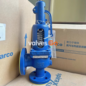
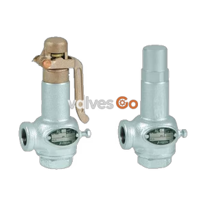
Yoshitake AL-301 closed type safety relief valve for steam applications up to 1.6 MPa and 220°C, featuring ductile cast iron body and stainless steel trim.
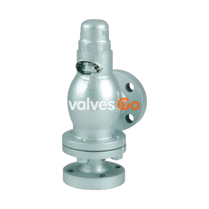
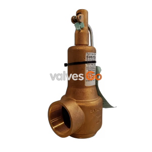
The Yoshitake AL-301 is a closed-type, lift-type safety relief valve designed for steam applications up to 1.6 MPa and 220°C. It features a ductile cast iron body and a stainless steel trim (valve and valve seat) for outstanding corrosion resistance and durability. The AL-300 series is widely used in small boilers, pressure vessels, instrumentation devices, and at the outlet of pressure reducing valves for safety alarming and relief. The series also includes the AL-300T and AL-301T models, which are designed with a PTFE disc for non-leakage sealing in air, water, and oil applications.
| Model | AL-300 | AL-301 |
|---|---|---|
| Structure | Closed type | Closed type |
| Application | Steam | Steam |
| Working pressure | 0.05-1.0 MPa | 0.05-1.6 MPa |
| Maximum temperature | 220°C | 220°C |
| Material (Valve case, Spring case) | Ductile cast iron | Ductile cast iron |
| Material (Valve, valve seat) | Cast bronze | Stainless steel |
| Connection | JIS 10K FF flanged | JIS 10K FF flanged |
JIS 16K FF flanged when working pressure is more than 1.0 MPa.
| Model | AL-300T | AL-301T |
|---|---|---|
| Structure | Closed type | Closed type |
| Application | Air, Cold and hot water, Oil, Other non-dangerous fluid | Air, Cold and hot water, Oil, Other non-dangerous fluid |
| Working pressure | 0.05-1.0 MPa | 0.05-1.3 MPa |
| Maximum temperature | 150°C | 150°C |
| Material (Valve case, Spring case) | Ductile cast iron | Ductile cast iron |
| Material (Valve, valve seat) | Cast bronze and PTFE | Stainless steel and PTFE |
| Connection | JIS 10K FF flanged | JIS 10K FF flanged |
JIS 16K FF flanged when working pressure is more than 1.0 MPa.
| Nominal size | L (mm) | H (mm) | H1 (mm) | d (mm) | Flow area (mm²) | Weight (kg) |
|---|---|---|---|---|---|---|
| 15A | 90 | 245 | 108 | 25 | 49.1 | 4.7 |
| 20A | 90 | 245 | 108 | 25 | 49.1 | 5.0 |
| 25A | 90 | 245 | 108 | 25 | 49.1 | 6.2 |
| 32A | 91 | 285 | 115 | 37 | 107.6 | 8.6 |
| 40A | 91 | 285 | 115 | 38 | 113.5 | 8.8 |
| 50A | 105 | 311 | 132 | 50 | 196.4 | 12.6 |
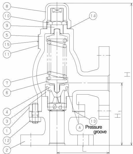
| Nominal size | L (mm) | H (mm) | H1 (mm) | d (mm) | Flow area (mm²) | Weight (kg) |
|---|---|---|---|---|---|---|
| 15A | 90 | 245 | 108 | 29 | 66.1 | 4.7 |
| 20A | 90 | 245 | 108 | 29 | 66.1 | 5.0 |
| 25A | 90 | 245 | 108 | 29 | 66.1 | 6.2 |
| 32A | 91 | 285 | 115 | 37 | 107.6 | 8.6 |
| 40A | 91 | 285 | 115 | 37 | 107.6 | 8.8 |
| 50A | 105 | 311 | 132 | 50 | 196.4 | 12.6 |
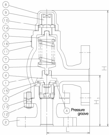
As the inlet pressure approaches the opening pressure, the force of fluid pushing up the valve approaches the force pressing down the valve. The safety relief valve starts to discharge when the inlet pressure reaches around 3% below the opening pressure, and the fluid accumulates gradually on the pressure groove. When the fluid pressure reaches the opening pressure, the valve pops.
Since the inlet pressure of the safety relief valve decreases when the fluid is released into the atmosphere by the pop action of the valve, the fluid lift force is lowered. At this point, the repelling force of the spring becomes larger than the force of fluid lift and thus the valve closes.
Yoshitake Safety Valves / Relief Valves
AF and AL series safety and relief valves for overpressure protection of steam, water, and air equipment.