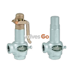
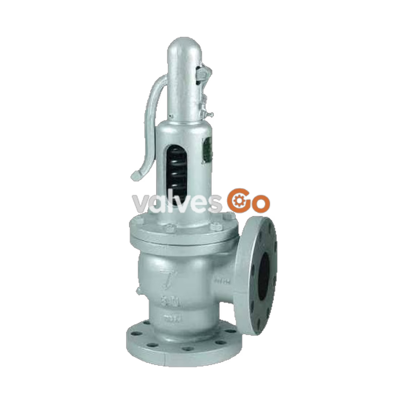
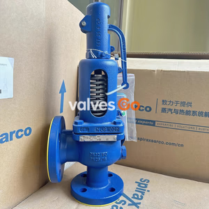
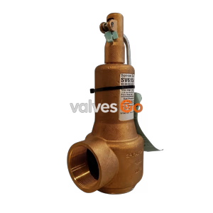
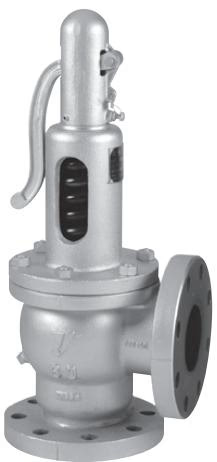
The Yoshitake AL-6 is an open lever type safety relief valve specifically designed for steam applications. It supports a working pressure range of 0.05 to 1.5 MPa and a maximum operating temperature of 220°C. The valve features a durable construction with a ductile cast iron spring case and cast stainless steel valve and valve seat, ensuring reliable performance in demanding environments. Available in nominal sizes from 65A to 150A, it utilizes JIS 10K FF or JIS 16K FF flanged connections depending on the operating pressure.
A key feature of the AL-6 is its lift lever mechanism, which allows a discharge inspection to be manually performed at more than 75% of the opening pressure.
Specifications
| Structure | Open lever type |
|---|
| Application | Steam |
| Working pressure | 0.05 to 1.5 MPa *1 |
| Max. temperature | 220°C |
| Material (Spring case) | Ductile cast iron |
| Material (Valve, valve seat) | Cast stainless steel |
| Connection | JIS 10K FF / 16K FF flanged *2 |
*1 Maximum working pressure for 150A is 0.8 MPa (JIS 10K FF). *2 JIS 16K FF flanged when working pressure is more than 1.0 MPa.
WARNING
- Do not use the product for equipment or device which cannot allow valve seat leakage. The product has allowable valve seat leakage and does not close completely (valve seat leakage cannot be zero).
- Do not use the product for equipment or device which vibrates excessively.
- Do not adjust (or change) set pressure.
Dimensions and Weights
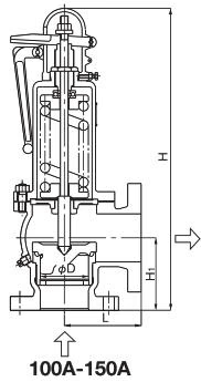
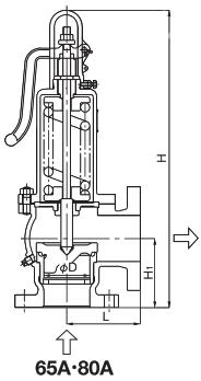
| Nominal size | L (mm) | H1 (mm) | H (mm) | Flow area (mm²) | Weight (kg) |
|---|
| 65A | 120 | 120 | 479 | 331.9 | 20.2 |
| 80A | 130 | 130 (132) | 493 (495) | 441.8 | 24.0 |
| 100A | 160 | 150 (152) | 626 (628) | 785.4 | 44.0 |
| 125A | 200 | 205 (207) | 835 (837) | 1227.2 | 88.0 |
| 150A | 210 | 215 | 893 | 1767.2 | 113.0 |
- The values in parentheses are the dimensions of JIS 16K FF flanged.
Structure
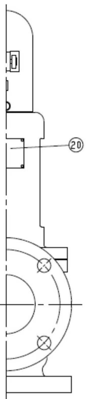
| No. | Part name | No. | Part name |
|---|
| 1 | Body | 11 | Lock nut |
| 2 | Spring case | 12 | Spring |
| 3 | Cap | 14 | Lever |
| 4 | Valve seat | 15 | Stud bolt & nut |
| 5 | Valve | 16 | Pin |
| 6 | Spindle | 17 | Nut |
| 7 | Guide plate | 18 | Bolt |
| 8 | Spindle guide | 19 | Plug |
| 9 | Spring plate | 20 | Name Plate |
| 10 | Adjusting screw | 21 | Gasket |
| | 22 | Split pin |
| | 23 | Spindle Ring |
Operation
Blowout operation As inlet pressure of the product rises and approaches opening pressure, the force of fluid pushing up the valve approaches the force of the spring pressing down the valve, and then the product commences to blow. The fluid starts to leak by the simmering and accumulates gradually on the pressure groove. When the fluid pressure reaches the specified opening pressure the valve pops.
Closing operation Since the inlet pressure of the safety relief valve decreases when the fluid is released into the atmosphere by the pop action of the valve, the force of fluid lift is lowered. At this point, the repelling force of the spring becomes larger than the force of fluid lift and thus the valve closes. In addition, since the safety relief valve blows, the pressure of fluid entering into the back of the valve (back pressure) adds to the closing force.
Installation
WARNING
- Do not install any closing device such as a stop valve at inlet and outlet sides of the product.
- Install an exhaust pipe on outlet side of the product, and lead it to a place where there is no risk of physical damage even if fluid blows out.
- Do not disassemble the product unnecessarily.
Installation Cautions
- Before installing the product, remove foreign substances and scale from the piping.
- When installing the product, confirm the direction of fluid flow with the inlet and outlet of the product respectively, and install the product correctly.
- Install the product vertically with the cap facing upward.
- Securely support and fasten the pipes.
- Connect the product to the pipes securely.
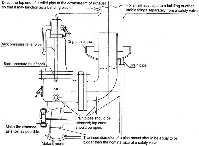
- Inner diameters of pipe mount and of exhaust pipe shall be equal to or more than those of each inlet and outlet of the product.
Pipe mount of safety relief valve
- Pipe mount should have sufficient strength and rigidity against shear stress, compressive stress and bending stress which are induced by reaction force in opposite direction of the exhaust through the axis of the exhaust pipe.
- Pressure loss in pipe mount leads to decrease in the discharge amount and to unstable operation of the product. To prevent them from happening, install the product vertically as close as possible to the can body and the header.
- Inner diameter of pipe mount shall be more than that of the product inlet.
Exhaust pipe of safety relief valve
- Install exhaust pipe and drip pan elbow so that the product cannot be subject to the stress caused by thermal expansion of the equipment and by expansion or contraction of the exhaust pipe due to thermal action of blowout.
- Inner diameter of exhaust pipe shall be more than that of the product outlet to avoid improper back pressure.
Maintenance
WARNING
- Do not touch the product/pipes with bare hands when touching them or operating the lever.
- Do not touch the product unless it is necessary.
- When checking the operation of the product, wear earplugs and stand clear of exhaust pipe end during inspection. Do not look down or touch the open end of the exhaust pipe.
- Do not disassemble the product.
Daily inspection Check the following items while the system is in operation:
- Corrosion or crack on the product.
- Leakage from the product under normal working pressure (check it visually and aurally).
- Leakage from connection between the product and piping.
Monthly inspection
- Check that there is no loose piping at inlet and outlet sides of the product.
- Check that the operation of the product by making fluid pressure 75% or more of set pressure and lifting the lever.
Troubleshooting
- Does not stop blowing: Scale stuck on contact surface between valve and valve seat; Sliding portions of the valve and valve seat do not move smoothly; The normal working pressure exceeds the closing pressure.
- Lever cannot be lifted: Inlet pressure is low; Sliding portions do not move smoothly.
- After lever operation, the product does not stop blowing: Scale stuck on contact surface.
- Fluid leakage at outlet side can be confirmed by sound: Scale stuck on contact surface; Damage on contact surface; Excessive vibration is applied to the product; Pressure difference is too small.
- Blows at pressure lower than the set pressure: Product specifications are not consistent with usage condition; Pressure gauge is out of order.