PN25
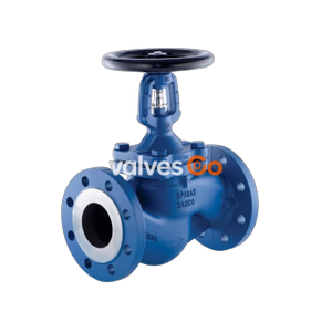
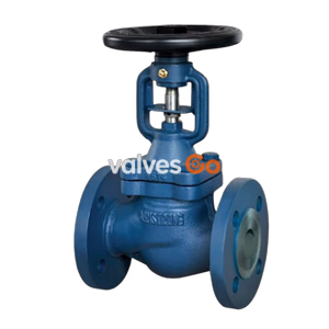
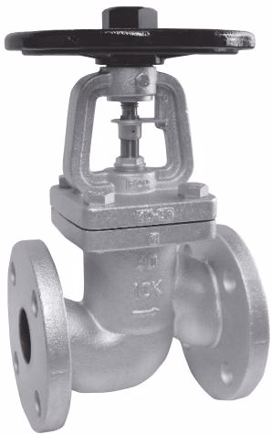
Yoshitake BSV-20F and BSV-10F ductile cast iron bellows seal globe valves. Features SUS316Ti bellows, zero gland leakage, handling steam and fluids up to 350°C and 2.8 MPa. JIS flanged.
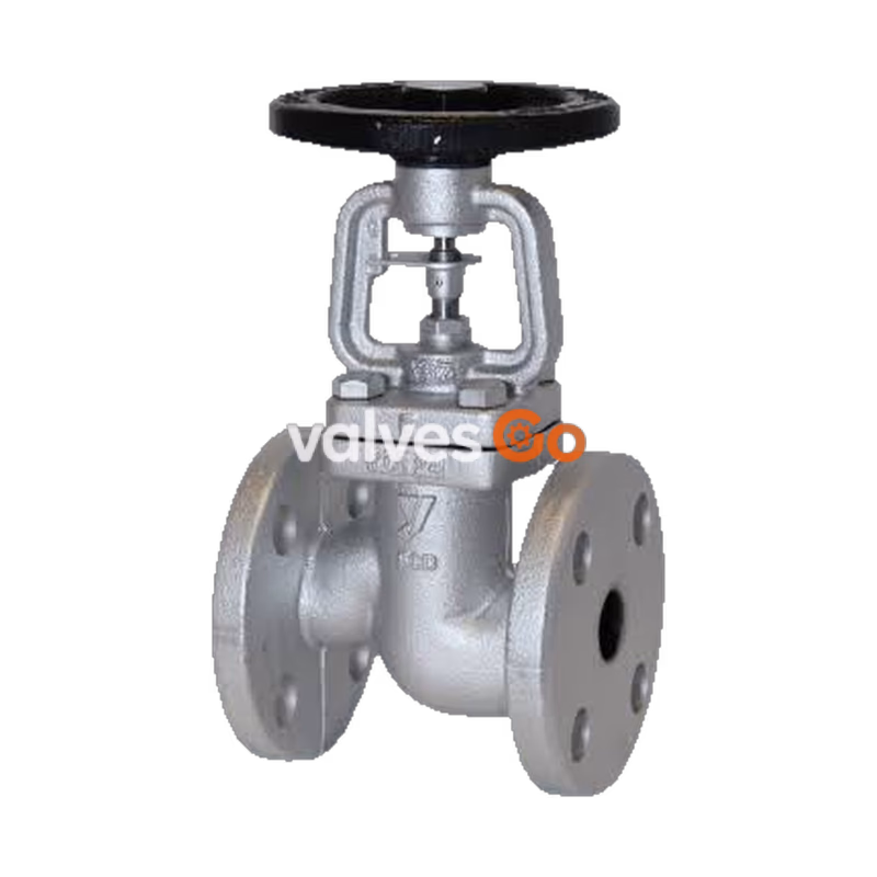
The Yoshitake BSV-20F and BSV-10F are ductile cast iron bellows seal globe valves designed to provide superior isolation for steam, air, cold and hot water, oil, and other non-dangerous fluids. Engineered with a highly durable SUS316Ti stainless steel bellows and stainless steel valve internals (reinforced with Stellite), these valves completely eliminate gland leakage and the need for frequent maintenance. The BSV-10F features JIS 10K FF flanged connections for up to 1.4 MPa, while the heavy-duty BSV-20F utilizes JIS 20K RF flanges to handle pressures up to 2.8 MPa and temperatures up to 350°C. Both models ensure safe and highly reliable performance in demanding industrial piping systems.
| Model | BSV-10F | BSV-20F |
|---|---|---|
| Application | Steam, Air, cold and hot water, oil, other non-dangerous fluid | Steam, Air, cold and hot water, oil, other non-dangerous fluid |
| Max. Pressure | 1.4 MPa *1 | 2.8 MPa *1 (15A-100A) 2.0 MPa *1 (125A-150A) |
| Max. Temperature | 300°C *1 | 350°C *1 |
| Body Material | Ductile cast iron | Ductile cast iron |
| Bonnet Material | Ductile cast iron | Ductile cast iron |
| Valve Material | Stainless steel | Stainless steel |
| Seat Material | Stainless steel | Stainless steel |
| Bellows Material | Stainless steel (SUS316Ti) | Stainless steel (SUS316Ti) |
| Connection | JIS 10K FF flanged | JIS 20K RF flanged |
1: The relationship between the operating pressure and operating temperature is based on JIS B2051 pressure-temperature standard.Note: Valve is closed at the time of shipment from the factory.
| Nominal Size | d | H | D1 | L | Weight (kg) |
|---|---|---|---|---|---|
| 15A | 15 | 184 | 125 | 108 | 3.5 |
| 20A | 20 | 184 | 125 | 117 | 4.0 |
| 25A | 25 | 188.5 | 125 | 127 | 5.5 |
| 32A | 32 | 193 | 125 | 140 | 6.5 |
| 40A | 40 | 235.5 | 180 | 165 | 9.5 |
| 50A | 50 | 235.5 | 180 | 203 | 11.5 |
| 65A | 65 | 252.5 | 200 | 216 | 15.0 |
| 80A | 80 | 272.5 | 200 | 241 | 18.5 |
| 100A | 100 | 348 | 250 | 292 | 30.0 |
| 125A | 125 | 358.5 | 300 | 356 | 48.0 |
| 150A | 150 | 440.5 | 400 | 406 | 67.0 |
| 200A | 200 | 570.5 | 450 | 495 | 115.0 |
| Nominal Size | d | H | D1 | L | Weight (kg) |
|---|---|---|---|---|---|
| 15A | 15 | 184 | 125 | 110 | 4.0 |
| 20A | 20 | 184 | 125 | 120 | 4.5 |
| 25A | 25 | 188.5 | 125 | 130 | 5.5 |
| 32A | 32 | 193 | 125 | 160 | 7.5 |
| 40A | 40 | 235.5 | 180 | 180 | 10.5 |
| 50A | 50 | 235.5 | 180 | 230 | 12.5 |
| 65A | 65 | 252.5 | 200 | 292 | 17.5 |
| 80A | 80 | 272.5 | 200 | 318 | 22.0 |
| 100A | 100 | 348 | 250 | 356 | 36.5 |
| 125A | 125 | 380 | 300 | 400 | 51.0 |
| 150A | 150 | 427 | 400 | 444 | 68.0 |
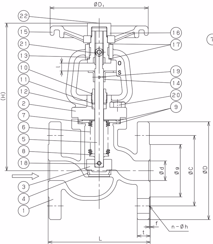
| No. | Name of Parts | Material |
|---|---|---|
| 1 | Body | Ductile Cast Iron (FCD450) |
| 2 | Bonnet | Ductile Cast Iron (FCD450) |
| 3 | Valve | Stainless Steel + Stellite |
| 4 | Valve Seat | Stainless Steel + Stellite |
| 5 | Spindle | Stainless Steel (SUS304 equivalent) |
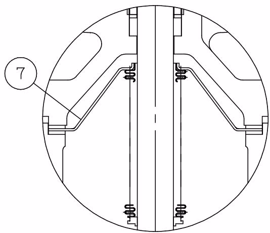
| 6 | Bellows | Stainless Steel (SUS316Ti equivalent) |
| 7 | Top Plate | Stainless Steel (SUS304 equivalent) |
| 8 | Bottom Plate | Stainless Steel (SUS304 equivalent) |
| 9 | Gasket | Expanded Graphite |
| 10 | Gland Nut | Stainless Steel (SUS304 equivalent) |
| 11 | Gland Washer | Stainless Steel (SUS304 equivalent) |
| 12 | Gland Packing | Expanded Graphite |
| 13 | Sleeve | Steel |
| 14 | Stopper | Steel |
| 15 | Handle | Ductile Cast Iron (FCD450) |
| 16 | Handle Nut | Steel |
| 17 | Sleeve Washer | Stainless Steel (SUS304 equivalent) |
| 18 | Pin | Stainless Steel |
| 19 | Pin | Stainless Steel |
| 20 | Bolt | Steel |
| 21 | Lock Bolt | Steel |
| 22 | Name Plate | Aluminium |
Caution
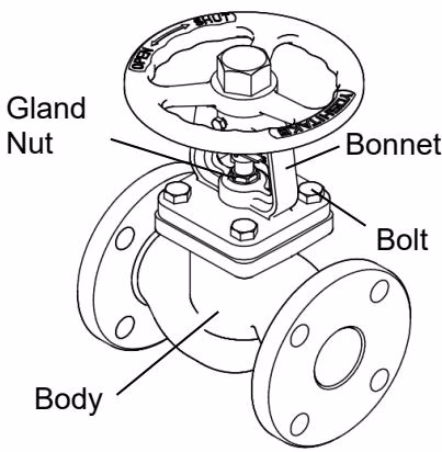
To use the valve for high-temperature fluids (approximately 200°C or higher), raise the valve temperature to the operating temperature, and then tighten the bolts additionally. For additional tightening, ensure that the valve is open, and tighten the bolts in a diagonal sequence from a low torque to the tightening torque as listed in the table below using a torque wrench. Tightening should be done gradually and evenly.
Additional Tightening Torque:
| Nominal Size | Bolt width across flats (mm) | Tightening torque (N·m) |
|---|---|---|
| 15-20A | 17 | 20 |
| 25-32A | 17 | 30 |
| 40-50A | 19 | 40 |
| 65A | 19 | 50 |
| 80-125A | 24 | 70 |
| 150-250A | 24 | 100 |
Warning
Before applying fluid, make sure that there is no danger if the fluid flows into the end of the piping. Failure to follow this notice may result in property damage due to fluid leakage.
Caution
Operation Torque Limits:
| Nominal Size | 15A | 20A | 25A | 32A | 40A | 50A | 65A | 80A | 100A | 125A | 150A | 200A | 250A |
|---|---|---|---|---|---|---|---|---|---|---|---|---|---|
| Torque Limit (N·m) | 20 | 20 | 25 | 30 | 50 | 50 | 80 | 110 | 160 | 245 | 300 | 300 | 300 |
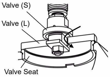
Sizes 200A and larger are equipped with Valve (S) to reduce the opening torque. When opening the valve, first rotate the Handle by approximately one full turn to open the Valve (S) and allow the differential pressure between the inlet and outlet pressures to reduce before continuing to operate the Handle.
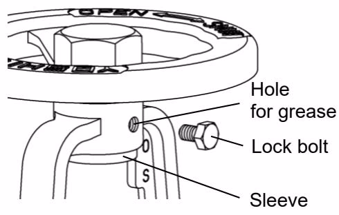
Tighten the lock bolt if it is necessary to fix the handle. When applying grease to the sleeve, remove the lock bolt and put grease into the screw hole (recommendation: Henkel LOCTITE LB 8150).
| Trouble | Cause | Remedy |
|---|---|---|
| Leakage from between the body and the bonnet | Stress relief of gasket. | Tighten the bolt additionally. If leakage does not stop after retightening, replace the product. |
| Leakage from the gland packing part | Damage of the bellows. | Tighten the gland nut. Then, replace the product immediately. |
| Leakage from the valve and/or valve seat on complete closing | 1. The valve and/or valve seat are damaged. 2. Foreign matter caught. | 1. Replace the product with a new one. 2. Remove the foreign substance. |
| Operation torque of the handle is abnormally large | 1. Poor lubrication of the sleeve. 2. Foreign substance is stuck on spindle and screw part. | 1. Apply grease to the sleeve. 2. Remove the foreign substance. |
| Abnormal sound | Each screw is loose. | Retighten the loosened parts. |
Warning
Completely discharge the pressure inside of the product, line and equipment before inspection and maintenance. For high temperature fluid, cool down the product till it can be touched with bare hands. Failure to follow this notice may result in injury or burns due to residual pressure.
Please perform annual inspections to maintain the product's optimal performance. Check for normal switching operation, abnormal sounds, and any signs of external leakage.
Explore similar products in our catalog