PN25
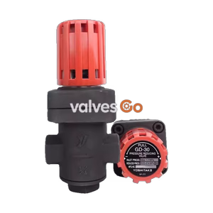
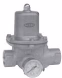
Yoshitake GD-26GS direct type pressure reducing valve for air and non-dangerous fluids. Cast stainless steel body, EPDM seals, and JIS Rc screwed connection.
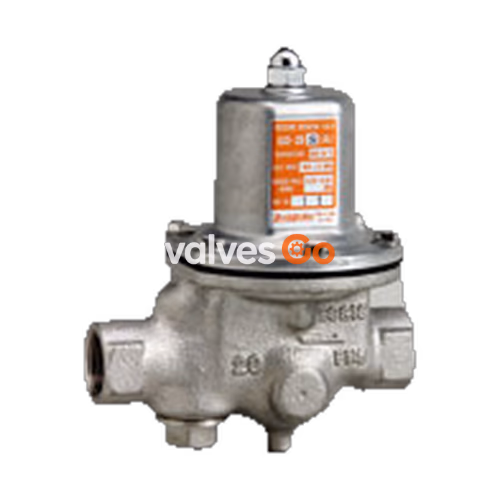
Yoshitake GD-26GS direct type pressure reducing valve is designed for air and other non-dangerous fluids. Constructed with cast stainless steel wetted parts and EPDM seals, it provides reliable pressure control up to 1.0 MPa inlet pressure. The GD-27GS model offers the same performance with flanged connections.
NOTE
For medium including oil, use fluorine rubber (FKM) for the disc and diaphragm. Otherwise, standard EPDM disc and diaphragm may be broken. Please contact the manufacturer when using for gas containing oil.
| Specification | Details |
|---|---|
| Model | GD-26GS / GD-27GS |
| Application | Air, Other non-dangerous fluids |
| Inlet Pressure | 1.0 MPa or less |
| Reduced Pressure | (A) 0.05-0.35 MPa (B) 0.3-0.7 MPa |
| Application Temperature | 5-90℃ |
| Minimum Differential Pressure | 0.05 MPa |
| Max. Pressure Reduction Ratio | 10:1 |
| Body / Valve Seat | Cast stainless steel |
| Valve Disc / Diaphragm | EPDM |
| Connection | GD-26GS: JIS Rc screwed GD-27GS: JIS 10K FF flanged |
GD-26GS (JIS Rc screwed)
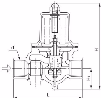
| Nominal Size | d | L (mm) | H (mm) | H1 (mm) | Weight (kg) |
|---|---|---|---|---|---|
| 20A | Rc 3/4 | 135 | 170 | 41 | 2.2 |
| 25A | Rc 1 | 135 | 170 | 41 | 2.2 |
| 32A | Rc 1-1/4 | 180 | 224 | 57 | 4.7 |
| 40A | Rc 1-1/2 | 180 | 224 | 57 | 4.5 |
| 50A | Rc 2 | 200 | 239.5 | 61 | 6.5 |
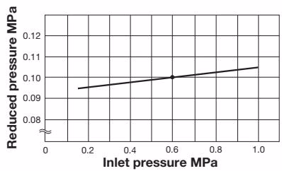
This chart shows variation in reduced pressure when the inlet pressure of 0.6 MPa is changed between 0.15 MPa and 1.0 MPa while the reduced pressure is set at 0.1 MPa.
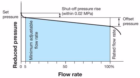
| Nominal Size | Pressure Range | Offset Pressure |
|---|---|---|
| 15-100A | (A) 0.05-0.35 MPa | Within 0.05 MPa |
| 15-100A | (B) 0.3-0.7 MPa | Within 0.10 MPa |
Rated Cv Value Table
| Nominal size | 15A | 20A | 25A | 32A | 40A | 50A | 65A | 80A | 100A |
|---|---|---|---|---|---|---|---|---|---|
| Rated Cv value | 2 | 2.3 | 3.5 | 6 | 7 | 11 | 21 | 26 | 38 |

PRECAUTION
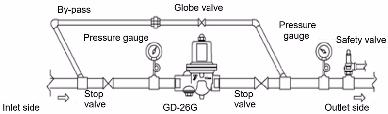
When installing a safety relief valve for equipment protection at the outlet side of the product, connect a blow-off pipe to the outlet side of the safety relief valve, and lead it to a place where there is no risk of physical damage even if fluid blows out.
INSTALLATION TIPS
| Trouble | Cause | Remedy |
|---|---|---|
| Reduced pressure does not reach the desired value | 1. Working pressure is improper. 2. Nominal size is too small. 3. Strainer is clogged. 4. Pressure adjustment is improper. | 1. Correct the working pressure. 2. Replace product with proper nominal size. 3. Clean the strainer. 4. Readjust pressure. |
| Abnormal pressure rises at the outlet side | 1. Foreign substances stuck between disc and valve seat. 2. O-ring or diaphragm is damaged. 3. Leakage from the globe valve of bypass line. | 1. Disassemble and remove foreign substances. 2. Replace O-ring / diaphragm. 3. Repair or replace the globe valve. |
| Abnormal sound | 1. Nominal size is too large. 2. Pressure reduction ratio is too large. 3. Quick operating valve is nearby. | 1. Replace with proper size. 2. Reduce pressure in two stages. 3. Keep a large distance between valves. |
Explore similar products in our catalog