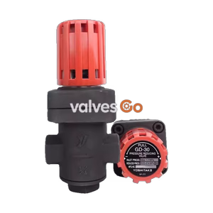
Yoshitake GD-46SP water pressure reducing valve (part of the GD-46 Series) enables shortening a construction work period since water pressure inspection can be performed easily by turning the cap upside down with the valve installed. It is primarily used for individual water supply in residential complexes to ensure that water is supplied at a regulated pressure.
Features
- Reduced noise. Can be used even late at night.
- Water pressure inspection can be performed easily by turning the cap upside down with the valve installed.
- Pressure balance structure can keep the reduced pressure at a constant level without being affected by inlet pressure.
- Attached pressure gauge joint allows a pressure gauge to be installed while water is supplied so that the set pressure can be checked easily.
- Noise characteristics and flow characteristics conform to the "Quality Criterion on Materials" of Urban Renaissance Agency in Japan.
Specifications
| Specification | Detail |
|---|
| Nominal size | 20A |
| Application | City water |
| Inlet pressure | 1.0 MPa or less |
| Reduced pressure | (A) 0.05-0.10 MPa [Standard setting: 0.09 MPa]
(B) 0.10-0.22 MPa [Standard setting: 0.20 MPa]
(C) 0.20-0.30 MPa [Standard setting: 0.25 MPa] |
| Minimum differential pressure | 0.02 MPa |
| Maximum pressure reduction ratio | 10:1 |
| Working temperature | Without pipe end core: 5-90℃
Equipped with pipe end core: 5-40℃
Equipped with check valve: 5-60℃ |
| Minimum adjustable flow rate | 0.5 L/min |
| Rated flow rate | Without check valve: 50 L/min (Differential pressure before and after valve: 0.10 MPa or more)
Equipped with check valve: 30 L/min (Differential pressure before and after valve: 0.10 MPa or more) |
| Pressure check function | Pressure gauge joint (JIS Rc 1/8 screwed) |
| Outlet withstand pressure | 1.2 times the maximum working pressure of outlet side |
Material
- Body: Cast bronze (NPb-treated)
- Spindle: Dezincification resistant material
- Valve disc: Synthetic rubber/Stainless Steel
- Diaphragm: Synthetic rubber
Additional Specifications Notes
- Available with pressure gauge (type A or type D) as an optional extra (for 0.5 MPa).
- The accuracy of a pressure gauge is ±3% F.S.
- The strainer is 60 mesh.
- The product is set to the pressure reducing valve function when it is delivered from the factory.
- An incombustible material is used for heat insulating material.
- Stop valve is not made with dezincification resistant material.
Dimensions and Weights
| Model | Connection (Inlet x outlet) | L (mm) | Weight (kg) |
|---|
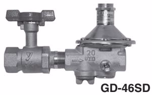
| GD-46SP / 46SPC | Rc 3/4 x R 3/4 | 247.5 | 1.6 |
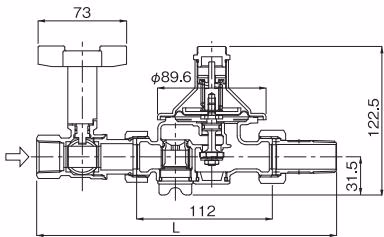 (Equipped with stop valve)
Dimensions of the Heat Insulating Material
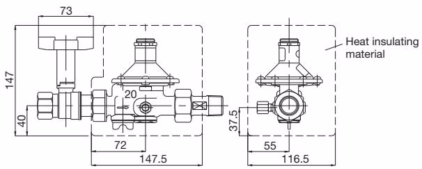 (GD-46SP)
Note
The heat insulating material is common to all GD-46 Series valves. However, no heat insulating material is used for the water stop valve.
Characteristic Curves
Flow Characteristic Chart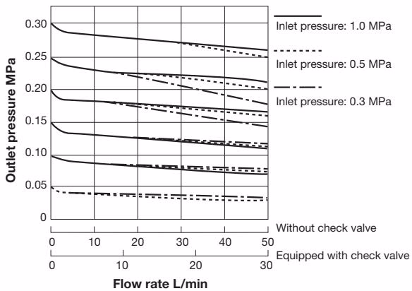
Noise Characteristic Chart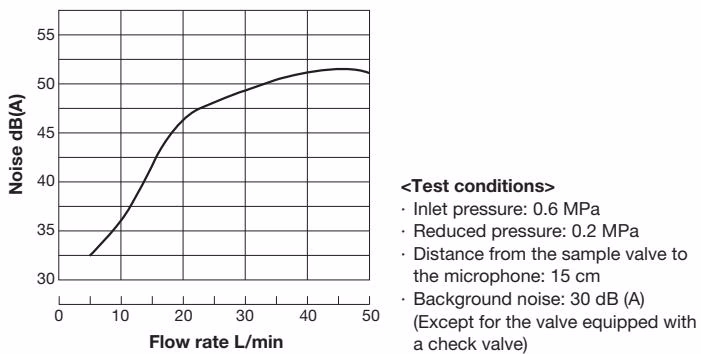
Pressure Characteristic Chart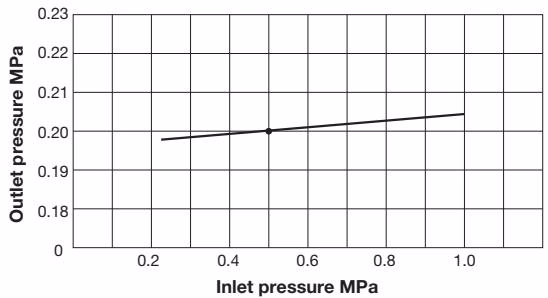 This chart shows variation in reduced pressure when the inlet pressure of 0.5 MPa is changed between 0.22 MPa and 1.0 MPa while the reduced pressure is set at 0.2 MPa.
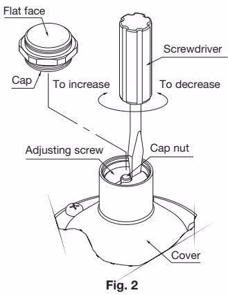
How to Adjust the Pressure
- Screw the pressure gauge into the pressure gauge joint (Fig. 1).
- Remove the cap. By checking the pressure gauge, turn the adjusting screw to adjust the reduce pressure to a desired level. (Fig. 2).
- The reduced pressure increases when the adjusting screw is turned clockwise.
- The reduced pressure decreases when the adjusting screw is turned counterclockwise.
- After reduced pressure adjustment, attach the cap with the flat face up.
- Remove the pressure gauge.
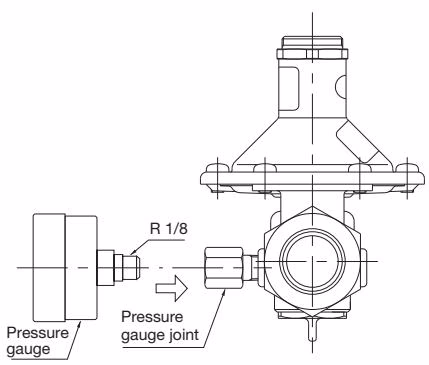 (Fig. 1)
 (Fig. 2)
Screwdriver Recommendation
Use a keystone tip screwdriver of 4.5 to 6 mm in nominal width for slotted head screws. Set the screwdriver in the slot of the adjusting screw avoiding the cap nut attached in the center of the screw, and adjust the reduced pressure.
Notes on Installation
- Arrow mark on the body must match with flow direction when installing.
- Parallel Installation or vertical installation to the piping is available.
- Install after eliminating the dusts, scale, and sands from the piping.
- Do not touch the adjusting screw unnecessarily because setting pressure is adjusted to standard setting pressure.
- Clean one or two times more per year regularly because if the dust, scale and sands are stuck in the strainer, water would not come out smoothly. Foreign substance accumulates especially in the first plumbing, so check the strainer soon after starting water supply.
- Caution on piping installation of a vinyl chloride tubing. If the adhesive agent for the vinyl chloride tubing flows in the product, synthetic rubber may be involved in, so please be careful when installing.
- Use the polystyrene foam as insulation material.
Cautions
- Before connecting the reducing valve to the piping, remove the foreign materials from the piping. If foreign materials are introduced into the reducing valve, it cannot operate as it should and may be damaged.
- To attach water shut of valve to reducing valve, make sure there is no inclination (misalignment of the piping center). If there is an inclination, it causes outside leakage because the sealing performance of the gasket is impaired.
- When installed in a closed piping, the reducing valve is damaged due to volume expansion of the fluid caused by temperature increase.
- Do not connect the reducing valve to a dissimilar metal pipe that can cause a potential difference, to avoid corrosion of the valve or its parts.
Water Pressure Inspection Procedure

Switching procedure of GD-46 PRV
- Be sure to check that there is no internal pressure in the piping before water pressure inspection. If internal pressure remains inside, remove it.
- Remove the cap and turn it out (make concave portion upward), and screw it firmly onto the spring cover. (Fig. 1)
- Do not screw the cap when there is internal pressure.
- On water pressure inspection, be sure to check the concave portion of the cap is screwed in upward direction, and conduct the water pressure inspection at 1.75 MPa or less.
- Take the internal pressure, and be sure to return the cap to the original position (making planar position upward) after water pressure inspection. (Fig. 2)
- If the cap does not return to its original position, the product cannot functions as a pressure reducing valve.
Bypass function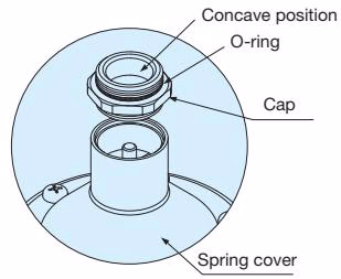 (Fig. 1)
Pressure reduction function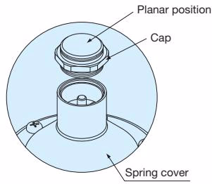 (Fig. 2)
Troubleshooting
| Problem | Possible Cause | Corrective Action |
|---|
| Low flow rate | • Strainer is clogged.
• Setting pressure is low. | • Clean the strainer.
• Adjust the pressure by following the adjusting steps. |
| Secondary pressure is higher than the set pressure | • The cap is left in water pressure test status. | • Flat surface part of cap should be upside. |
| External leakage | • Set screw, valve cap, strainer cap is loose.
• O-ring or gasket is damaged.
• Joint of pressure gauge is loosen. | • Retighten the round head screw, valve cap, and the strainer cap.
• Replace the O-ring and gasket with a new one.
• Remove the joint. Apply seal tape to the thread and attach the joint to the valve body. |