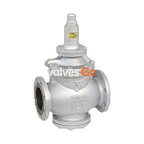
Yoshitake GP-27 is a pilot-type, internal sensing piston pressure reducing valve designed for steam applications. It features a built-in strainer, ductile cast iron body, and a 10:1 maximum pressure reduction ratio. The valve responds immediately to fluctuations in inlet pressure and changes in flow rate, maintaining a constant reduced pressure without the need for auxiliary power.
Features
- Large capacity and distinguished performance. Can respond immediately to the fluctuation of inlet pressure and the change of flow rate to keep reduced pressure at a constant level.
- Quite simple structure, less prone to fail and easy to handle.
- Easy pressure adjustment and wide set pressure range.
- No need for auxiliary power (air or electricity). Compactness makes plumbing work easy.
- Compliant with SHASE-S106 Pressure Reducing Valves (by the Society of Heating, Air-Conditioning and Sanitary Engineers of Japan).
Specifications
| Specification | Value |
|---|
| Model | GP-27 |
| Application | Steam |
| Inlet pressure | 0.1-1.0 MPa |
| Reduced pressure | 0.03-0.8 MPa (80% or less of inlet pressure) |
| Minimum differential pressure | 0.07 MPa |
| Maximum pressure reduction ratio | 10:1 |
| Maximum temperature | 220℃ |
| Valve seat leakage | 0.05% or less of rated flow rate |
| Connection | JIS 10K FF flanged |
Materials
| Part | Material |
|---|
| Body | Ductile cast iron |
| Main valve, valve seat | Stainless steel |
| Pilot valve, pilot valve seat | Stainless steel |
| Piston, Cylinder | Bronze |
| Diaphragm | Stainless steel |
Dimensions and Weights
| Nominal size | L (mm) | H (mm) | H1 (mm) | Weight (kg) |
|---|
| 125A | 375 | 627 | 162 | 90.0 |
| 150A | 420 | 686 | 190 | 135.0 |
| 200A | 490 | 765 | 220 | 204.0 |

Construction and Operation
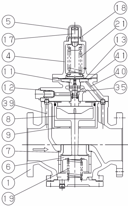
The pressure-reducing valve reduces pressure by throttling the valve. It is composed of the main valve and main valve seat for throttling, and an adjusting spring, diaphragm, pilot valve, and piston for pressure sensing and activation.
- When the pressure-reducing valve is mounted correctly, releasing the compression of the adjusting spring closes the main valve and pilot valve. Slowly opening the gate valve allows high-pressure fluid to flow in, applying inlet pressure to the downside of the main valve and pilot valve.
- Turning the adjusting screw compresses the spring and flexes the diaphragm, opening the pilot valve.
- Inlet pressure enters the upside of the piston via the pilot valve, overriding the main valve spring and opening the main valve.
- Reduced pressure is led to the diaphragm chamber, balancing with the adjusting spring load to control the pilot valve travel.
- The change in pilot valve travel adjusts the flow rate to the piston, controlling the main valve travel to obtain the appropriate reduced pressure.
Sizing and Selection
Specifications Selection Chart
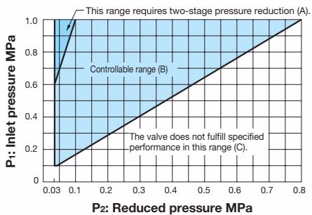
Based on the selection chart, select a pressure reducing valve in the optimum manner. Find the intersection point of the inlet pressure (P1) and the reduced pressure (P2).
- Range (A): Two-stage pressure reduction is required. Separate two valves by at least 3 meters.
- Range (B): Pressures are controllable with a single pressure reducing valve.
- Range (C): The valve does not fulfill specified performance.
Characteristic Charts
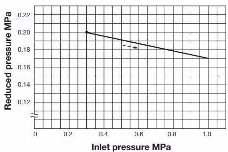
This chart shows the variation in reduced pressure when the inlet pressure is changed between 0.3 MPa and 1.0 MPa while the reduced pressure is set at 0.2 MPa.
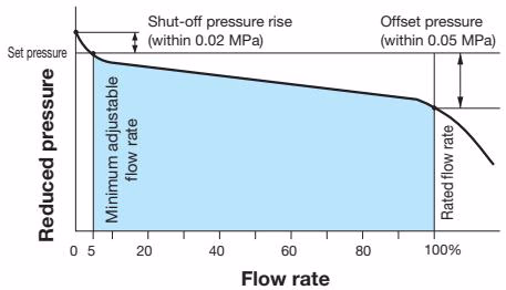
- Shut-off pressure rise: 0.02 MPa or less
- Offset: 0.05 MPa or less
Nominal Size Selection Chart (For Steam)
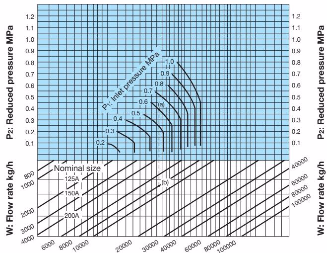
Example: When selecting the nominal size for an inlet pressure of 0.6 MPa, reduced pressure of 0.4 MPa, and steam flow rate of 8000 kg/h:
- Find intersection point (A) of 0.6 MPa inlet pressure and 0.4 MPa reduced pressure.
- Trace down vertically to find intersection point (B) with the flow rate of 8000 kg/h.
- Since (B) is between 125A and 150A, select the larger size, 150A.
Nominal Size Selection Calculation
An appropriate nominal size can be calculated by obtaining the Cv value for the operating conditions.
When P2 > P1 / 2: Cv = W * k / (138 * √(ΔP * (P1 + P2)))
When P2 ≤ P1 / 2: Cv = W * k / (120 * P1)
- W: Max. steam flow rate [kg/h]
- P1: Inlet pressure [MPa A]
- P2: Reduced pressure [MPa A]
- ΔP: P1 - P2 [MPa]
- k: 1 + 0.0013 × (super-heated steam temp. [℃] - saturated steam temp. [℃])
| Nominal size | 125A | 150A | 200A |
|---|
| Cv value | 100 | 144 | 230 |
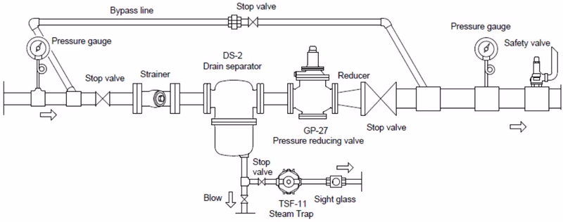
Installation
Piping Example
Installation Precautions
- Hold the valve with lifting equipment while piping due to heavy weight.
- Install the valve perpendicularly to horizontal lines.
- Provide a by-pass line.
- If installing a safety valve at the outlet side, connect a relief pipe to safely guide the steam out.
- When the pressure-reducing ratio is large, install a reducer to keep flow velocity below 30 m/s.
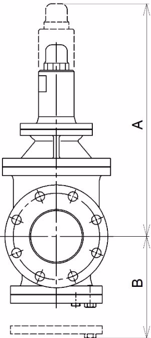
Provide space on the top and bottom of the valve for easy disassembly and inspection:
- 125A: A = 690mm, B = 370mm
- 150A: A = 725mm, B = 435mm
- 200A: A = 780mm, B = 495mm
Operation and Adjustment
Precaution for Operation
- Do not touch the product with bare hands directly to prevent scalds.
- Before applying steam, ensure piping joints are securely connected and there is no risk when steam flows.
Operating Cautions
- Close stop valves before and after the reducing valve, and blow off foreign matter via the by-pass line before operation.
- Secondary pressure at the by-pass line must be lower than the set pressure.
- Turn the adjusting screw slowly to prevent hunting or water hammer.
- Discharge fluid completely before stopping operation for an extended period.
Adjusting Procedure
- Close inlet and outlet stop valves. Blow off fluid via the by-pass line to remove foreign matter. Close the by-pass valve.
- Remove the cap, loosen the locknut and adjusting screw, and release the spring (no compression).
- Slowly open the inlet stop valve, and adjust the outlet stop valve to allow a little fluid flow.
- Slowly turn the adjusting screw in the direction of the casted "H" arrow on the spring chamber to increase pressure, or opposite to decrease, observing the outlet pressure gauge.
- Slowly open the outlet stop valve and readjust to the desired pressure.
- Tighten the lock nut and attach the cap.
Maintenance and Troubleshooting
Troubleshooting
| Trouble | Cause | Remedy |
|---|
| Reduced pressure of desired level is not obtained | Working pressure is improper. | Correct the working pressure. |
| The strainer is clogged. | Disassemble and clean. |
| Foreign matter between piston and cylinder. | Disassemble, remove matter, and polish scratches. Replace if necessary. |
| Nominal size is too small. | Change nominal size. |
| Pressure is not adjusted correctly. | Readjust pressure. |
| Strainer installed before valve is clogged. | Disassemble and clean. |
| Abnormal pressure rises at the outlet | Pressure gauge is faulty. | Replace it. |
| Foreign substances or scratches between main valve and seat. | Disassemble, clean, and lap. |
| Foreign substances or scratches between pilot valve and seat. | Disassemble, clean, and lap. Replace if necessary. |
| Foreign matter between piston and cylinder. | Disassemble, clean, polish, or replace. |
| Trap is not provided for dead-end line. | Install a trap device. |
| By-pass valve is leaking. | Repair or replace. |
| Abnormal sound / Unstable operation | Nominal size is too large. | Change nominal size. |
| Pressure reducing ratio is too large. | Reduce pressure in two stages. |
| Drainage problem. | Install a trap device. |
| Abrupt OPEN/CLOSE valve is too close. | Allow as much distance as possible. |
Disassembly and Reassembly
Disassembly Precautions
- Disassembly and maintenance must be conducted by professionals.
- Ensure stop valves are closed and all internal pressure and condensate are discharged before disassembling.
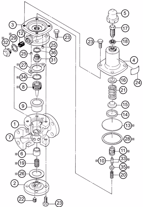
Precautions for reassembly:
- Check for damage on the main valve, main valve seat, pilot valve, and pilot valve seat. Lap if necessary.
- If the main valve seat is damaged beyond lapping, replace the entire product (the seat cannot be replaced independently).
- Confirm sliding parts move smoothly.
- Apply a heat/steam resistant lubricant (e.g., SOLVEST No.110 paste) to the bottom seal area of the diaphragm.
Recommended Replacement Intervals:
- Pilot Valve Set (10, 11, 33, 35): 5 years
- Strainer (12): 5 years
- Diaphragm (13): 2 years
- Gaskets (26, 27, 29): 2 years
- Piston Ring (34): 3 years