Cast Iron

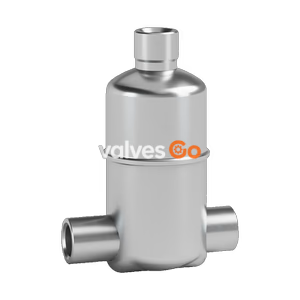
Yoshitake LD-51 self-operated gas trap. Automatically discharges condensate from gas lines without external power. Soft seal type, 0-100 kPa, suitable for hydrogen and air.
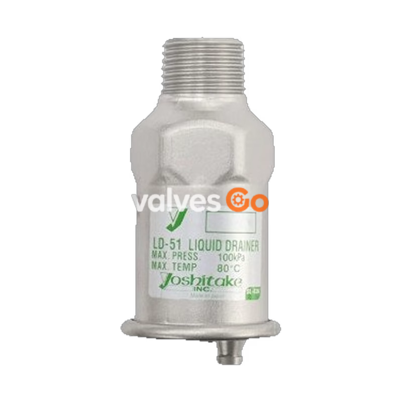
Yoshitake LD-51 is a self-operated drain valve for gas lines that automatically discharges condensate without external power. Featuring a soft seal structure, it is designed to contribute to a hydrogen society and is suitable for air, other non-dangerous gases, and hydrogen gas (contact for details).
| Specification | Value |
|---|---|
| Model | LD-51 |
| Nominal Size | 15A |
| Application | Air, Other non-dangerous gas, Hydrogen gas (*Contact for details) |
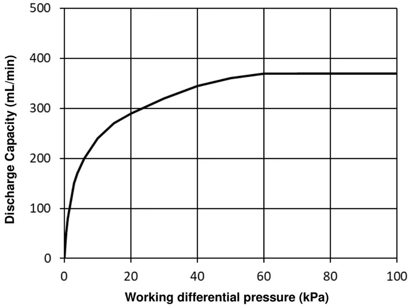
| Working Pressure | 0–100 kPa |
| Working Temperature | 5–80°C |
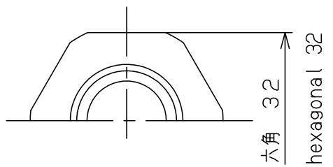
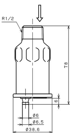
| Inlet Connection | JIS R 1/2 screwed |
| Outlet Connection | Hose joint (φ6) |
Related Models
The catalog also includes the LD-16 model, which supports higher working pressures (0–1.0 MPa) and is available in nominal sizes from 15A to 25A with a JIS Rc1/4 outlet connection.
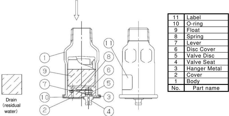
| No. | Part Name | Material |
|---|---|---|
| 1 | Body | Stainless Steel (SUS304) |
| 2 | Cover | Stainless Steel (SUS304) |
| 3 | Hanger Metal | Stainless Steel (SUS304) |
| 4 | Valve Seat | Stainless Steel (SUS304) |
| 5 | Valve Disc | FKM |
| 6 | Disc Cover | Stainless Steel (SUS304) |
| 7 | Lever | Stainless Steel (SUS304) |
| 8 | Spring | Stainless Steel (SUS304) |
| 9 | Float | PP & FKM (Heat-resistance plastic & Fluororubber) |
| 10 | O-ring | FKM |
| 11 | Label | Polyester |
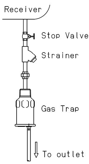
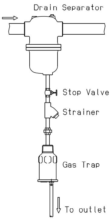
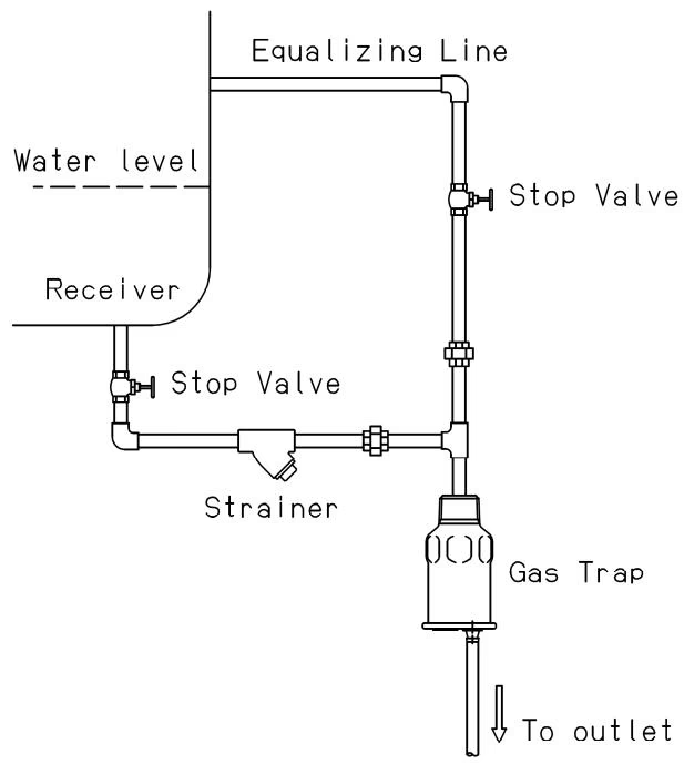
Installation Precautions
Maintenance Precautions
Please carry out daily inspections to maintain product functionality and performance.
| Item | How to inspect | Actions to be taken |
|---|---|---|
| Working state | Confirm that condensate is being discharged. (If no condensate is present internally, the valve will remain closed.) | See Troubleshooting |
| Valve seat leakage | Check visually | See Troubleshooting |
| Outside leakage | Check visually | See Troubleshooting |
Note: Although service life may vary depending on usage conditions, it is recommended to replace the product every 3 to 5 years, along with daily inspections.
| Trouble | Cause | Remedy |
|---|---|---|
| Condensate is not discharged. | 1. Stop valve at inlet or outlet is closed. 2. Pressure difference is too high. 3. Clogging of the valve seat hole due to foreign substances. 4. The float is damaged. 5. Damaged or deformed due to abnormal pressure increase caused by freezing or water hammer, etc. | 1. Open the stop valve. 2. Reduce to appropriate pressure difference. 3. Replace the product and install a strainer on the inlet side. 4. Replace the product. 5. Replace the product and use it within the working pressure range. |
| Condensate does not stop discharging. | 1. Foreign substances or damage exist between valve disc and valve seat. 2. Product specifications are insufficient for usage condition. | 1. Replace the product. 2. Recheck the selection of the product. |
| Outside leakage. | 1. Damaged or Deformed due to abnormal pressure increase caused by freezing or water hammer, etc. 2. O-ring is damaged. | 1. Replace the product and use it within the working pressure range. 2. Replace the product. |
Yoshitake Compressed Air Drain Traps
LD and TSF-AT series compressed-air drain traps for automatic condensate removal from air systems.
Explore similar products in our catalog