Cast Iron

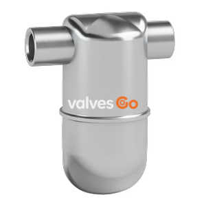
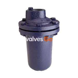
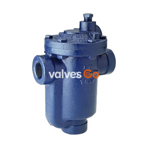
Yoshitake TB-20F is an inverted bucket steam trap featuring a ductile cast iron body and stainless steel internals. Operates up to 1.0 MPa and 220°C.
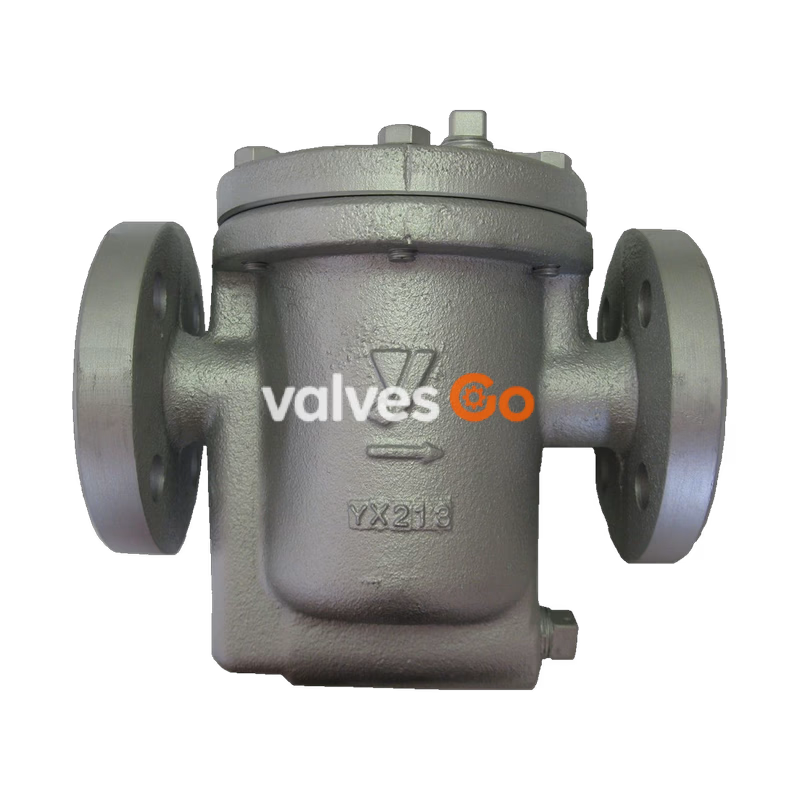
Yoshitake TB-20F is an inverted bucket steam trap designed for steam condensate applications. Featuring a ductile cast iron body and stainless steel internal parts, it provides excellent durability and reliable performance. The unique internal structure includes a hemispherical valve and a stainless steel upper plug for enhanced wear resistance. This trap achieves super energy saving by utilizing intermittent operation to remove the air adiabatic wall in the heat exchanger, considerably increasing heat efficiency. The TB-20F model features JIS 10K FF flanged connections and operates at a maximum pressure of 1.0 MPa and temperatures up to 220°C.
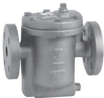
| Model | TB-20 | TB-20F |
|---|---|---|
| Nominal Size | 15A, 20A, 25A | 15A, 20A, 25A |
| Connection | JIS Rc screwed, JIS 20K FF flanged | JIS 10K FF flanged |
| Application | Steam condensate | Steam condensate |
| Maximum Pressure | 2.0 MPa | 1.0 MPa |
| Max. Differential Pressure (A) | 0.3 MPa | 0.3 MPa |
| Max. Differential Pressure (B) | 0.6 MPa | 0.6 MPa |
| Max. Differential Pressure (C) | 1.0 MPa | 1.0 MPa |
| Max. Differential Pressure (D) | 1.6 MPa | - |
| Maximum Temperature | 220°C | 220°C |
| Material (Body) | Ductile cast iron | Ductile cast iron |
| Material (Valve) | Stainless steel (Heat treated) | Stainless steel (Heat treated) |
| Material (Valve seat) | Stainless steel (Heat treated) | Stainless steel (Heat treated) |
Note
Available with ASME and EN flanged.
Recommendation
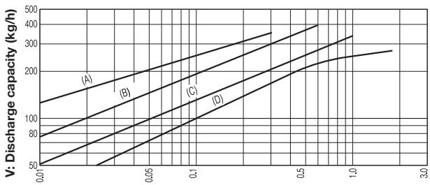
The discharge capacity shown here is a continuous discharge capacity at the indicated differential pressure. In general, select a steam trap with a safety factor twice or threefold the regular level.
TB-20F Dimensions (mm)
| Nominal size | L | H | H1 | A | Weight (kg) |
|---|---|---|---|---|---|
| 15A | 175 | 183 | 94 | 117 | 5.4 |
| 20A | 175 | 183 | 94 | 117 | 6.0 |
| 25A | 175 | 183 | 94 | 117 | 6.3 |
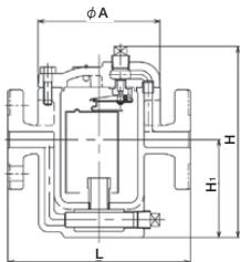
| Nominal size | L | H | H1 | A | Weight (kg) |
|---|---|---|---|---|---|
| 15A | 136 | 183 | 94 | 117 | 4.3 |
| 20A | 136 | 183 | 94 | 117 | 4.3 |
| 25A | 136 | 183 | 94 | 117 | 4.3 |
INFO
The dimensions of the product with JIS 10K FF flanged and the product with JIS 20K FF flanged are identical. The thickness of JIS 10K FF flanges conforms to that of JIS 20K FF flanges.
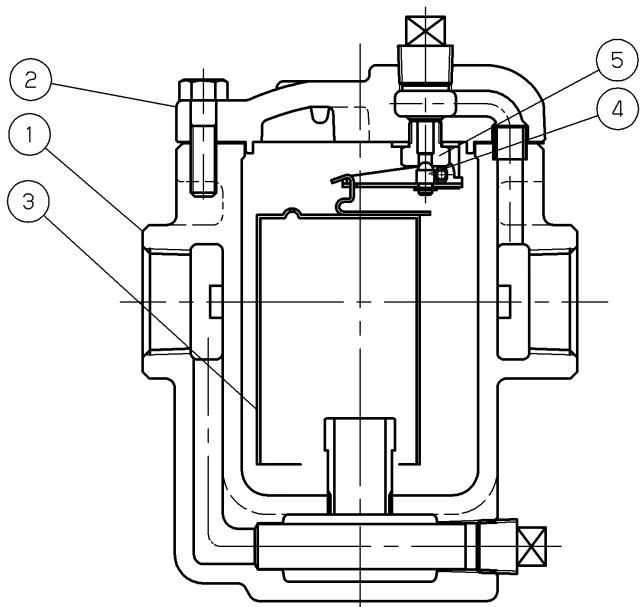
| No. | Name of parts |
|---|---|
| 1 | Body |
| 2 | Cover |
| 3 | Bucket P |
| 4 | Valve |
| 5 | Valve seat |
(1) Start of discharge The air in a trap is pushed up with low-temperature condensate, passes along an upper valve seat, and is discharged at an outlet side. Low-temperature condensate also passes along the inside and the perimeter of a bucket by inflow of high-temperature condensate, and is discharged from an upper valve seat to an outlet side.
(2) Closing operation If steam enters in a bucket following high-temperature condensate, a bucket will come floating and will close a valve seat. If there is no inflow of condensate, carrying out a closed valve is continued.
(3) Operation to discharge condensate If condensate flows in again, a bucket will lose lift, and will sink. A valve will be opened and condensate will be discharged from a valve seat at an outlet side. Henceforth, the operation of (2) and (3) is repeated according to the amount of generating of condensate.
Warnings
Cautions
| Trouble | Cause | Measure |
|---|---|---|
| No discharge | 1. Operating pressure is higher than the proper pressure of the trap. 2. Valve seat is clogged. 3. Bucket vent is clogged. 4. Screen is clogged. 5. Breakage of trap by freezing or water-hammer. | 1. Replace the trap. 2. Disassemble and clean the valve seat. 3. Disassemble and clean the bucket vent. 4. Disassemble and clean the screen. 5. Replace the trap. |
| Poor discharge | 1. Too low pressure difference due to high back pressure. 2. Screen is clogged. | 1. Examine inlet/outlet pressure. 2. Disassemble and clean the screen. |
| Continuous blowing off | 1. Foreign material between valve and valve seat. 2. Flaw or wear between valve and valve seat. 3. Low discharge capacity. 4. Lever holder is deformed. 5. Too high back pressure. 6. Disappearance of condensate. | 1. Disassemble and clean. 2. Replace by conversion kit. 3. Replace the trap. 4. Replace the trap. 5. Examine piping. 6. Make condensate flow into bucket. |
| Leakage to outside | 1. Leakage between body and cover. 2. Leakage around plug. 3. Breakage of trap by freezing. | 1. Replace gasket. 2. Rewind sealing tapes and reassemble plug. 3. Replace the trap. |
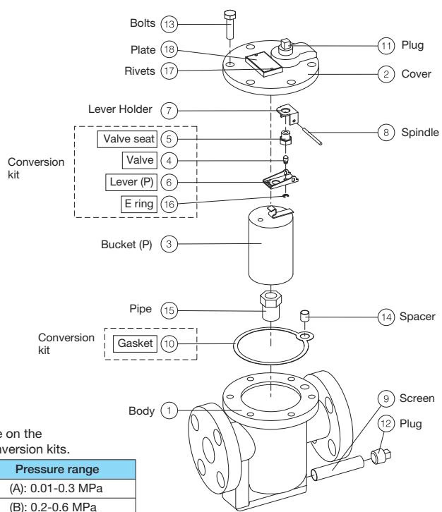
Conversion Kits
| No. | Pressure range |
|---|---|
| K-93070 | (A): 0.01 - 0.3 MPa |
| K-93071 | (B): 0.2 - 0.6 MPa |
| K-93072 | (C): 0.3 - 1.0 MPa |
| K-93073 | (D): 0.6 - 1.6 MPa |
Maintenance Cautions
Yoshitake Steam Traps / Inverted Bucket Steam Traps
TB series inverted bucket steam traps for reliable removal of condensate and air from steam equipment.
Explore similar products in our catalog