Cast Iron

Armstrong 30-DC Series forged steel automatic differential condensate controllers. Designed for syphon drainage or gravity drainage requiring increased velocity.
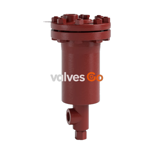
Armstrong 30-DC Series automatic differential condensate controllers (DC) are designed to function on applications where condensate must be lifted from a drain point or in gravity drainage applications where increased velocity will aid in condensate drainage.
When lifting from the drain point, often referred to as syphon drainage, the reduction in pressure that occurs when the condensate is elevated causes a portion of it to flash back into steam. Ordinary steam traps, unable to differentiate between flash steam and live steam, close and impede drainage. Increased velocity with gravity drainage will aid in drawing the condensate and air to the DC. This increased velocity is caused by an internal steam by-pass, controlled by a manual metering valve, so the condensate controller will automatically vent the by-pass or secondary steam. This is then directed to the condensate return line or collected for use in other heat exchangers.
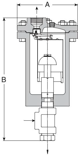
| Model No. | 33-DC | 34-DC | 35-DC | 36-DC |
|---|---|---|---|---|
| Inlet & Outlet Connections | 1" (25 mm) | 1-1/4" (32 mm) | 1-1/2" (40 mm) | 2" (50 mm) |
| Secondary Steam Conn. | 1/2" (15 mm) | 3/4" (20 mm) | 1" (25 mm) | 1" (25 mm) |
| "A" (Diameter) | 8" (203 mm) | 8-5/8" (219 mm) | 9-3/4" (248 mm) | 11-7/8" (302 mm) |
| "B" (Height) | 16-9/16" (420 mm) | 19-1/4" (489 mm) | 21-7/16" (544 mm) | 23-7/8" (607 mm) |
| Weight lb (kg) | 53 (24) | 73 (33) | 102 (46) | 184 (83) |
| Maximum Operating Pressure, Sat. Steam | 650 psi (44 bar) | 650 psi (44 bar) | 650 psi (44 bar) | 650 psi (44 bar) |
| Maximum Allowable Pressure (Vessel Design) | 1,080 psi @ 650°F (74 bar @ 343°C) | 1,130 psi @ 650°F (78 bar @ 343°C) | 1,015 psi @ 650°F (70 bar @ 343°C) | 1,100 psi @ 650°F (76 bar @ 343°C) |
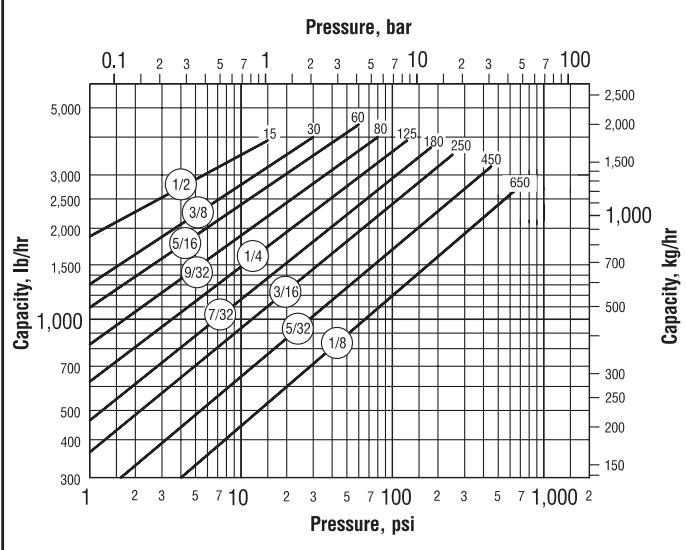
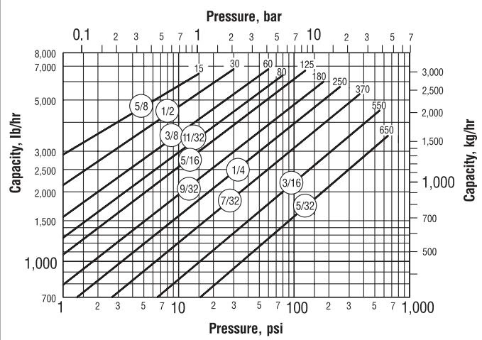
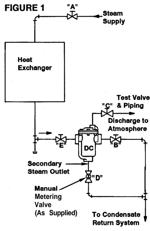
These instructions primarily cover the Condensate Controllers installed with the secondary steam being discharged back into the condensate return piping (See Figure 1 below). If the secondary steam discharge from the Controller is into a separate pipe header for re-use in other condensing units, the manual metering valve setting "D" may differ, depending upon the pressure of the secondary steam header.
Installation Recommendations
The following valve settings should be made on initial start-up of equipment. (Refer to Figure 1).
Close valve "B" on the condensate discharge of controller and open test valve "C". Condensate being discharged through the Controller is now observed at test valve piping to atmosphere. Note the cycle rate of condensate discharge. (This would be typical of the operation of a standard inverted bucket trap.)
Important
If the condensate discharge is continuous, never cycling, the Differential Controller selected may be too small for the required load.
Note
If the secondary steam from the Controller is discharging into a separate header, the required setting of the manual metering valve may exceed 1 full turn open under low differential pressure (ΔP) conditions. Test as described above for correct setting.
The Differential Condensate Controller should now be functioning normally with the manual metering valve and secondary steam flow at the correct setting to provide the highest heat transfer efficiency.
Once the Differential Condensate Controller is set, the manual metering valve setting should not be changed. The handle of the valve should be locked in place to prevent valve tampering by unauthorized personnel. Should the manual metering valve be closed to isolate the Controller during repairs, record its opening position and return to same when putting Controller back in operation.
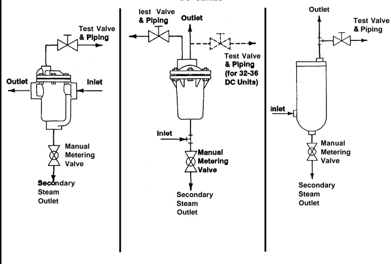
| 30-DC Series Model | Test Valve Piping Size |
|---|---|
| 32-DC | 1/2" |
| 33-DC | 1/2" |
| 34-DC | 1/2" |
| 35-DC | 3/4" |
| 36-DC | 1" |
Explore similar products in our catalog