Repairable

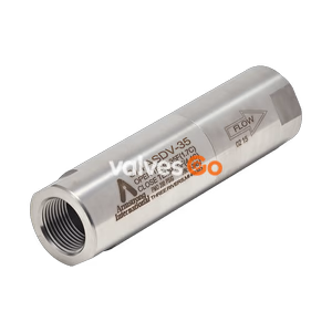
The Armstrong AB-3000 Bimetallic Steam Trap features a sealed stainless steel body and integral strainer. It handles up to 22 bar operating pressure and mounts via a 360° Universal Connector.
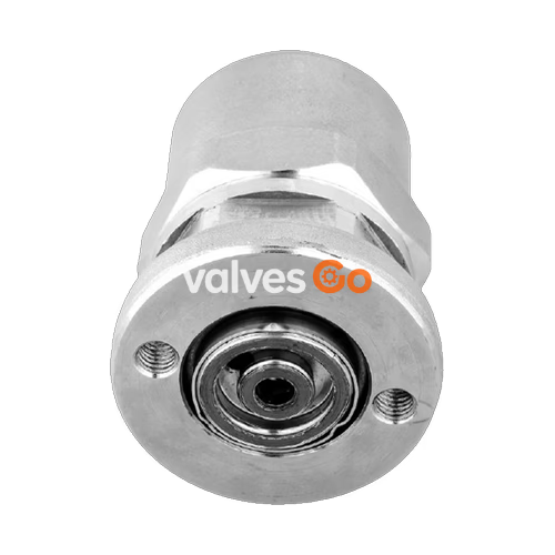
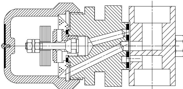
Armstrong AB-3000 Bimetallic Steam Trap operates by the effect that rising temperature has on bimetallic elements. It adjusts itself to changing conditions, as the increasing pressure on the valve is compensated by the curving of the bimetallic elements caused by the increasing temperature. At start-up, the bimetallic element is contracted and the valve is fully open, removing large condensate loads and non-condensable gases. When the system reaches steam temperature, the element expands, pulling the valve stem to close the valve.
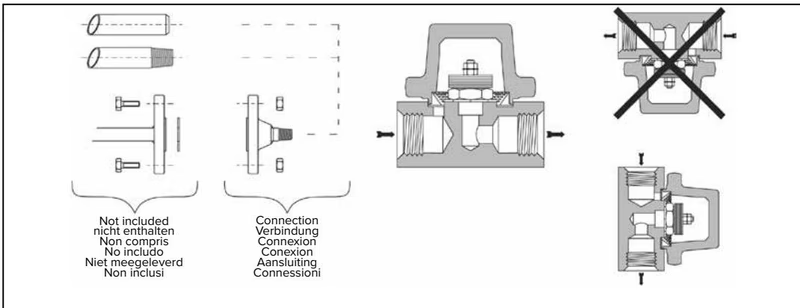
Armstrong’s AB-3000 has a sealed, stainless steel body that is lightweight, compact, and highly resistant to corrosion. The AB-3000 is repairable (body and cap can be unscrewed). It is piped through the Armstrong 360° Universal Connector or Trap Valve Station (TVS). This makes it easy to install and replace, as the trap can be removed while the connector remains in-line, saving labor costs and increasing flexibility.
Connections: Screwed BSPT and NPT, Socketweld, Flanged DIN (PN40) or ANSI (welded).
| Part | Material |
|---|---|
| Body | ASTM-A240 304L Stainless Steel / ASTM-A479 Type 304 |
| Cap | ASTM-A351 Gr CF8 |
| Valve | 440F / AICI-440C Chrome Steel |
| Seat | 303 Stainless Steel |
| Elements | Nickel Plated Bimetallic Disc |
| Strainer | 304 Stainless Steel |
| Gasket | 304 Stainless Steel Non-asbestos |
| Pipe Connections | 15 mm (1/2") | 20 mm (3/4") | 25 mm (1") |
|---|---|---|---|
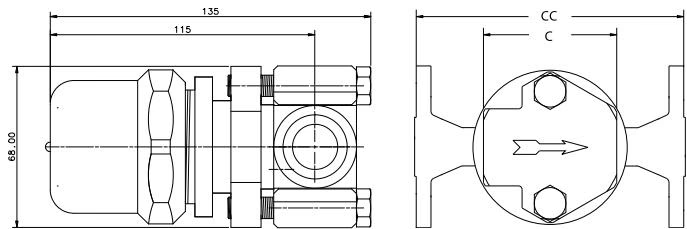
| "C" Face-to-Face (screwed & SW) | 60 mm | 60 mm | N/A |
| "CC" Face-to-Face (flanged PN40) | 150 mm | 150 mm | 160 mm |
| Weight (screwed & SW) | 1.9 kg | 1.9 kg | N/A |
| Weight (flanged PN40) | 4.3 kg | 4.5 kg | 4.7 kg |
Note: Standard flanges are in carbon steel, stainless steel flanges are optional. Other flange sizes, ratings, and face-to-face dimensions are available on request.
Before installation, verify that the maximum allowable pressure/temperature and maximum operating pressure of the trap are sufficient to handle the system design pressure and temperature.
WARNING
Due to the high temperatures of steam, it might be necessary to guard the traps for personnel safety.
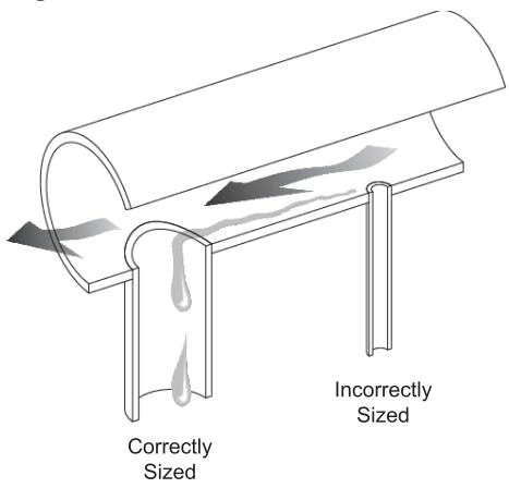
| Steam Main Size (in) | Drip Leg Diameter (in) | Supervised Warm-Up Min Length (in) | Automatic Warm-Up Min Length (in) |
|---|---|---|---|
| 1/2 | 1/2 | 10 | 28 |
| 3/4 | 3/4 | 10 | 28 |
| 1 | 1 | 10 | 28 |
| 2 | 2 | 10 | 28 |
| 3 | 3 | 10 | 28 |
| 4 | 4 | 10 | 28 |
| 6 | 4 | 10 | 28 |
| 8 | 4 | 12 | 28 |
| 10 | 6 | 15 | 28 |
| 12 | 6 | 18 | 28 |
| 14 | 8 | 21 | 28 |
| 16 | 8 | 24 | 28 |
| 18 | 10 | 27 | 28 |
| 20 | 10 | 30 | 30 |
| 24 | 12 | 36 | 36 |
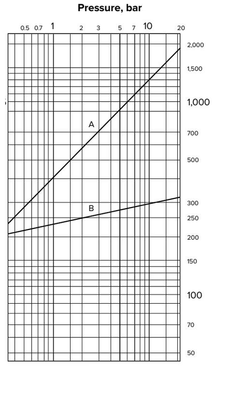
High-pressure drip traps should be tested at least three times per year. Normal trap operation is indicated by the trap discharging condensate continuously (modulating) or in cycles (on-off), accompanied by large amounts of flash steam.
DANGER
Equipment under pressure - Operating temperature > 100°C Make sure the trap is cold and depressurized before handling!

1. Cold Trap - No Discharge No condensate or steam coming to trap.
2. Steam Loss If the trap leaks or blows live steam, trouble may be due to:
3. Continuous Flow
Explore similar products in our catalog