


PN16

Armstrong B and BI Series cast iron float and thermostatic steam traps for continuous drainage and high air-venting capacity. Features thermostatic air vent and optional vacuum breaker.
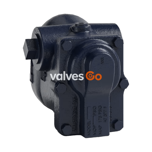
Armstrong B and BI Series float and thermostatic (F&T) steam traps combine high standards of performance and long life with economy for heating service where continuous drainage with high air-venting capacity is required. Because of the wide use of vacuum returns in systems of this type, the thermostatic air vent element is charged to give it the capability of compensated response to the pressure-temperature curve of steam at any pressure from less than 500 mm Hg (20") vacuum to 2 bar (30 psig) gauge. B and BI Series F&T traps will vent air at slightly below steam temperature throughout this entire range of operation.
All B Series traps, except the 1/2" and 3/4", have inlet connections on both sides of the body to provide flexibility in piping. The BI Series F&T traps in sizes 1/2", 3/4" and 1" feature the convenience of in-line connections with the same internals as the B Series.
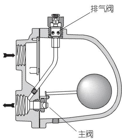
The working principle of the float trap is based on the opening and closing action of the lever float mechanism caused by the change of condensate level in the valve body.
Key Features:
Maximum allowable pressure (vessel design):
WARNING
Cast iron traps should not be used in systems where freezing, excessive hydraulic or thermal shock are present.
Connections: Screwed BSPT and NPT. Flanged EN 1092-1 or ASME B16.5 (screw on) on request.
| Component | Material |
|---|---|
| Body and cap | ASTM A48 Class 30 Cast Iron |
| Internals | All stainless steel — 304 |
| Valve | Stainless steel — 303 or 440 |
| Seat | Stainless steel — 303 (ASTM A582) / 440F in 1-1/2" and 2" |
| Thermostatic air vent | Stainless steel and bronze with phosphor bronze bellows, caged in stainless steel |
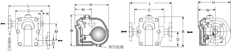
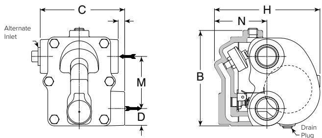
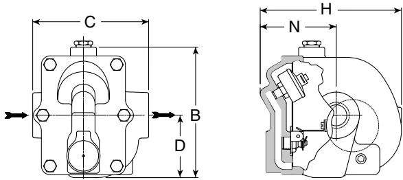
| Model No. | B2 / B3 | B4 | B5 | B6 | B8 | BI2 / BI3 / BI4 |
|---|---|---|---|---|---|---|
| Pipe Connections (mm) | 15 - 20 | 25 | 32 | 40 | 50 | 15 - 20 - 25 |
| "B" Height (mm) | 124 | 140 | 140 | 189 | 244 | 143 |
| "C" Face-to-Face (screwed) (mm) | 98 | 124 | 117 | 146 | 194 | 127 |
| "D" Bottom to Center (mm) | 22.2 | 25.4 | 31.0 | 36.5 | 42.9 | 68.0 |
| "H" Width (mm) | 137 | 152 | 197 | 214 | 295 | 168 |
| Weight in kg (screwed) | 2.7 | 3.9 | 5.0 | 8.6 | 18.1 | 4.4 |
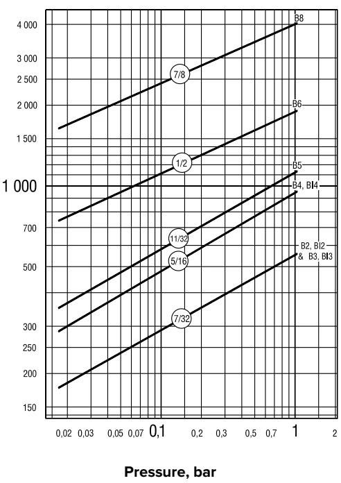
Integral vacuum breaker. Add suffix VB to model number.
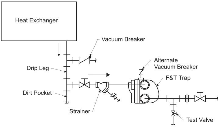
Many times, condensate will be retained ahead of steam traps because of the presence of a vacuum. To break a vacuum, air must be introduced into the system by means of a vacuum breaker. For maximum protection against freezing and water hammer in condensing equipment under modulated control, vacuum breakers are recommended. Armstrong B and BI Series F&T traps are available with integral vacuum breakers. Maximum pressure is 10 bar (150 psig).
DANGER
Do not use a conventional vacuum breaker open to the atmosphere in any system that incorporates a mechanical return system that carries pressure less than atmospheric pressure. This includes all return systems designated as vacuum returns, variable vacuum returns or subatmospheric returns.
Maintenance: Armstrong F&T steam traps are designed for easy accessibility during maintenance. The entire operating mechanism is attached to the cap. Pipe connections are made to the body. You should inspect the internal mechanisms of these traps at least once a year.




