


PN25

Armstrong GP-1000 Series internally piloted pressure reducing valves offer accurate regulation for steam, air, and gas with a 20:1 turndown ratio and +/-5% accuracy.
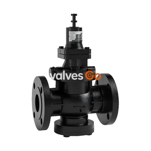
Armstrong GP-1000 Series valves are pilot-controlled for accurate regulation of pressure under wide-ranging flow. The internal pilot design eliminates the need for external components and piping. Internally piloted GP Series valves are capable of larger capacity and greater accuracy than direct-acting valves, providing a 20:1 turndown ratio and +/-5% set point accuracy.
Completely supported by piping, the lightweight GP Series valves install easily with NPT or flanged connections. A stainless steel diaphragm, hardened stainless steel working parts, and an integral removable strainer team up to provide high performance over a long, trouble-free service life. Valves are equipped with a single-seated main valve, piston valve rings for longer life, and an external adjusting screw with a locking nut. All working parts are renewable in-line, and the valves provide ANSI Class IV Shutoff. For air service, a Teflon® valve seat ensures a tight seal.
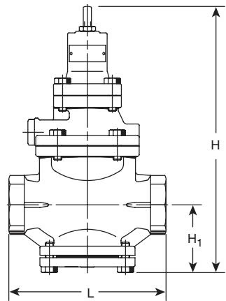
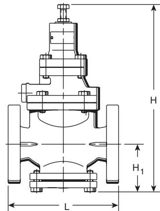
| Model Number | Inlet Pressure | Reduced Pressure | Spring Color | Application | Max Temp | Min Diff. | Body Material | Main Valve / Seat | Pilot Valve / Seat | Piston / Cylinder | Diaphragm |
|---|---|---|---|---|---|---|---|---|---|---|---|
| NPT GP-1000 | 15 - 250 psig (1 - 17 barg) | 7 - 125 psig (.48 - 8.6 barg) | Black | Steam | 450°F (232°C) | 7 psig (.48 barg) | Ductile Iron ASTM A536 | SS AISI 420 | SS AISI 403/420 | SS AISI 420 / SS AISI 403 | SS AISI 301 |
| NPT GP-1000 | 15 - 250 psig (1 - 17 barg) | 125 - 200 psig (8.6 - 13.8 barg) | Green | Steam | 450°F (232°C) | 7 psig (.48 barg) | Ductile Iron ASTM A536 | SS AISI 420 | SS AISI 403/420 | SS AISI 420 / SS AISI 403 | SS AISI 301 |
| 150 ANSI GP-1000 | 15 - 150 psig (1 - 10 barg) | 7 - 125 psig (.48 - 8.6 barg) | Black | Steam | 450°F (232°C) | 7 psig (.48 barg) | Ductile Iron ASTM A536 | SS AISI 420 | SS AISI 403/420 | Bronze / Bronze ASTM C36000 | SS AISI 301 |
| NPT GP-1000A | 15 - 150 psig (1 - 10 barg) | 7 - 125 psig (.48 - 8.6 barg) | Black | Air & Gas | 175°F (80°C) | 7 psig (.48 barg) | Ductile Iron ASTM A536 | SS AISI 420 / Brass w/NBR | SS AISI 403/420 | Bronze / Bronze ASTM C36000 | SS AISI 301 |
| 150 ANSI GP-1000A | 15 - 150 psig (1 - 10 barg) | 7 - 125 psig (.48 - 8.6 barg) | Black | Air & Gas | 175°F (80°C) | 7 psig (.48 barg) | Ductile Iron ASTM A536 | SS AISI 420 / Brass w/NBR | SS AISI 403/420 | Bronze / Bronze ASTM C36000 | SS AISI 301 |
| GP-1000SS / GP-1000AS | 15 - 150 psig (1 - 10 barg) | 7 - 125 psig (.48 - 8.6 barg) | Black | Steam | 450°F (232°C) | 7 psig (.48 barg) | SS AISI 304 | SS AISI 420 | SS AISI 403/420 | SS AISI 420 / SS AISI 403 | SS AISI 301 |
Notes: Sizes 2" (50 mm) and below are NPT connections. Sizes 2" (50 mm) and larger are flanged connections. GP-1000SS/GP-1000AS are available in 1/2" - 2" only and are flanged with NPT companion flanges.
| Size (in) | Size (mm) | L (in) | L (mm) | H (in) | H (mm) | H1 (in) | H1 (mm) | Weight lb (kg) | Cv Factor |
|---|---|---|---|---|---|---|---|---|---|
| 1/2 | 15 | 5-7/8 | 150 | 11-1/4 | 285 | 2-1/2 | 64 | 15-1/2 (7) | 1 |
| 3/4 | 20 | 6-1/8 | 155 | 11-1/4 | 285 | 2-1/2 | 64 | 15-1/2 (7) | 2.3 |
| 1 | 25 | 6-5/16 | 160 | 11-7/8 | 300 | 2-5/8 | 67 | 19 (8.5) | 4 |
| 1-1/4 | 32 | 7-1/2 | 190 | 12-3/4 | 323 | 3-1/4 | 82 | 25-1/2 (12) | 6.5 |
| 1-1/2 | 40 | 7-1/2 | 190 | 12-3/4 | 323 | 3-1/4 | 82 | 27-1/2 (12.5) | 9 |
| 2* | 50 | 8-11/16 | 220 | 13-5/8 | 347 | 3-11/16 | 93 | 40 (18) | 16 |
| 2-1/2 | 65 | 9-5/8 | 245 | 14 | 357 | 4 | 100 | 66 (30) | 25 |
| 3 | 80 | 11-3/8 | 290 | 15-7/8 | 404 | 4-13/16 | 122 | 77 (35) | 36 |
| 4 | 100 | 13 | 330 | 17-3/4 | 450 | 5-9/16 | 144 | 116 (53) | 64 |
Notes: GP-1000 is 1/2"-2" (20-50 mm) NPT, 2"- 4" (50-100 mm) ANSI 150 lb flanged. "L" Dimension for 2” 150# flange is 8-11/16” (220 mm).
| Inlet (bar) | Outlet (bar) | 15mm | 20mm | 25mm | 32mm | 40mm | 50mm | 65mm | 80mm | 100mm |
|---|---|---|---|---|---|---|---|---|---|---|
| 1.03 | 0.55 | 18 | 42 | 73 | 119 | 164 | 292 | 456 | 657 | 1,168 |
| 0.34 | 21 | 49 | 85 | 138 | 191 | 339 | 529 | 762 | 1,355 | |
| 2.07 | 1.59 | 23 | 53 | 92 | 149 | 206 | 366 | 572 | 824 | 1,464 |
| .34 - .48 | 35 | 80 | 139 | 225 | 312 | 555 | 867 | 1,248 | 2,219 | |
| 3.45 | 2.90 | 30 | 68 | 119 | 193 | 267 | 475 | 742 | 1,069 | 1,900 |
| 2.07 | 45 | 102 | 178 | 290 | 401 | 713 | 1,114 | 1,604 | 2,852 | |
| .34 - 1.17 | 50 | 115 | 201 | 326 | 452 | 803 | 1,255 | 1,807 | 3,212 | |
| 6.89 | 5.86 | 54 | 124 | 216 | 351 | 486 | 864 | 1,350 | 1,945 | 3,457 |
| 4.83 | 74 | 169 | 295 | 479 | 663 | 1,179 | 1,842 | 2,652 | 4,715 | |
| .34 - 2.9 | 89 | 205 | 356 | 578 | 801 | 1,423 | 2,224 | 3,203 | 5,694 | |
| 10.00 | 8.62 | 83 | 191 | 332 | 540 | 748 | 1,330 | 2,077 | 2,991 | 5,318 |
| 6.89 | 113 | 259 | 450 | 732 | 1,013 | 1,801 | 2,815 | 4,053 | 7,206 | |
| 5.52 | 128 | 295 | 513 | 834 | 1,155 | 2,054 | 3,209 | 4,621 | 8,215 | |
| .55 - 4.6 | 128 | 294 | 511 | 830 | 1,150 | 2,044 | 3,194 | 4,599 | 8,176 | |
| 13.79 | 11.72 | 104 | 240 | 417 | 678 | 938 | 1,668 | — | — | — |
| 10.34 | 131 | 302 | 525 | 853 | 1,181 | 2,099 | — | — | — | |
| 8.62 | 155 | 357 | 621 | 1,009 | 1,398 | 2,485 | — | — | — | |
| .68 - 6.3 | 167 | 383 | 666 | 1,082 | 1,499 | 2,665 | — | — | — | |
| 17.24 | 13.79 | 147 | 339 | 590 | 959 | 1,327 | 2,360 | — | — | — |
| 12.07 | 176 | 404 | 703 | 1,143 | 1,583 | 2,814 | — | — | — | |
| 10.34 | 197 | 454 | 790 | 1,283 | 1,776 | 3,158 | — | — | — | |
| .89 - 8.06 | 205 | 472 | 821 | 1,335 | 1,848 | 3,285 | — | — | — |
Note: For air capacities m3/hr, multiply steam capacities kg/hr by 1.35. For air capacities scfm, multiply steam capacities lb/hr by 0.36.
Installation Hints
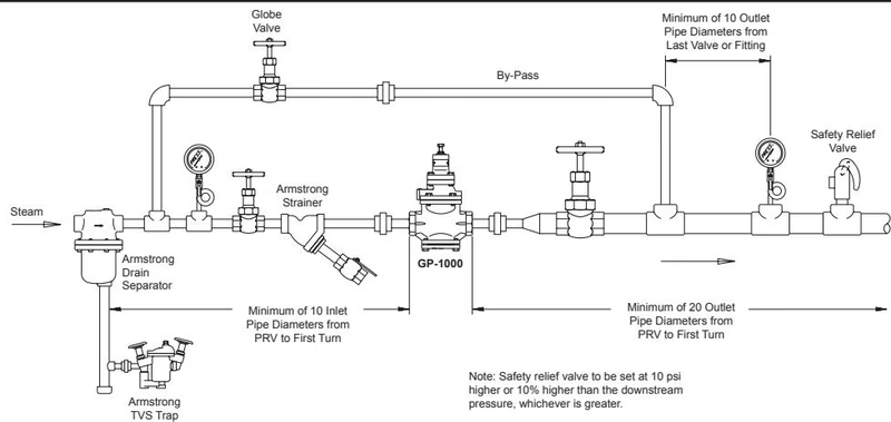
Improper adjustment of the pressure reducing valve may cause hunting, improper control, and possible damage to the valve itself. Adjust the valve as follows:
| Problem | Causes | Solutions |
|---|---|---|
| The desired pressure cannot be obtained. | The inlet pressure is too low or too high. | Change the pressure to the appropriate level. |
| The strainer in the pilot body is clogged. | Disassemble and clean the strainer. | |
| The piston-cylinder clearance is clogged. | Disassemble and clean the piston and cylinder. Refinish surface if flawed. | |
| The valve size is smaller than required. | Change to the appropriate valve size. | |
| The adjustment is not appropriate. | Readjust according to the adjustment procedure. | |
| The inlet strainer is clogged. | Disassemble and clean the strainer. | |
| The pressure gauge is not functioning. | Replace the gauge. | |
| The outlet pressure rises higher than specified. | The main valve or seat is contaminated. | Disassemble and clean the valve or seat. |
| The pilot valve or seat is contaminated. | Disassemble and clean the valve or seat. | |
| The piston-cylinder clearance is clogged. | Disassemble and clean the piston and cylinder. | |
| The bypass valve is leaking. | Repair or replace the bypass valve. | |
| Abnormal noise is heard. | The valve size is larger than required. | Install the correct size valve. |
| The reducing ratio is greater than 20:1. | Reduce pressure by staging with a second PRV. | |
| Water hammer. | Install a steam trap at the reducing valve inlet. | |
| Fast closing valve near the PRV. | Provide as long a distance as possible between the two valves. | |
| Others | Springs or diaphragms are damaged. | Replace all damaged springs or diaphragms. |
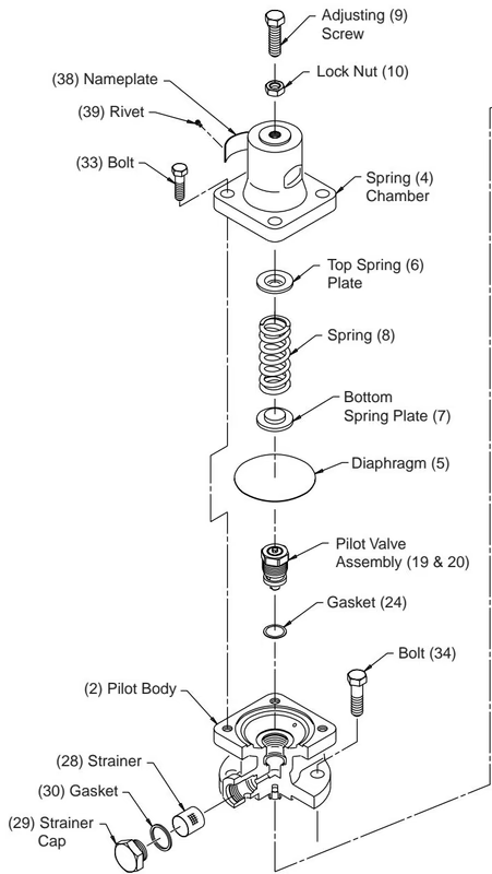
Disassembly Caution
Be sure that the isolation valves at the inlet and outlet side of the pressure reducing valve are closed and all internal pressure has been relieved before disassembly of the valve.
Pilot Valve Disassembly:
Piston Disassembly:
Main Valve Disassembly:
GP-1000 Lapping Procedure for Pilot Valve:
GP-1000 Lapping Procedure for Main Valve:
Explore similar products in our catalog



