

PN16

BURKERT 20000714 (Type 0330) direct-acting 2/2-way NC solenoid valve features stainless steel 1.4401 body, FKM seals, 4 mm orifice, NPT 1/4 ports, -1 to 3 bar rating, and 120 V AC coil.
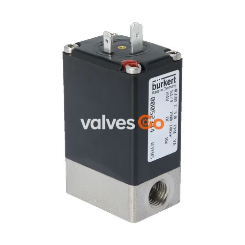
BURKERT 20000714 (Type 0330) is a direct-acting, media-separated 2/2-way pivoted armature solenoid valve designed for shut-off, dosing, and control of neutral or aggressive liquid and gaseous fluids. Configured in Circuit Function A (normally closed), the unit features a 4.0 mm nominal orifice, NPT 1/4 internal thread ports, a 1.4401 stainless steel valve body and seat, and high-integrity FKM seals. An epoxy-encapsulated Class H solenoid coil operates on 120 V AC at 60 Hz, delivering an inrush power of 30 VA and holding power of 15 VA (8 W). It handles vacuum down to -1.00 bar up to a positive gauge pressure of 3.00 bar, providing a flow coefficient Kv of 0.23 m³/h for water and a gas flow rate QNn of 255 l/min.
The valve utilizes pivoted armature technology where a flexible diaphragm hermetically isolates the magnetic coil assembly and internal mechanical movement from the wetted media path. This separation protects against internal corrosion and particulate accumulation caused by harsh chemical media, oxidizing acids, salts, and technical gases. Rated for 100% continuous duty cycle (100% ED) across an ambient operating span up to +55 °C and fluid temperatures from 0 °C to +90 °C, the assembly achieves response times of 8 to 15 ms for opening and closing under AC power. An integrated manual override facilitates system startup, functional testing, and emergency isolation.
| Parameter | Value |
|---|---|
| Model Article Number | 20000714 |
| Valve Type Family | Type 0330 |
| Circuit Function | A (2/2-way valve, direct-acting, normally closed) |
| Nominal Diameter (Orifice) | 4.0 mm (5/32") |
| Port Connection Type | Internal thread NPT 1/4 |
| Installation Length | 46 mm |
| Flow Value Kv (Water) | 0.23 m³/h |
| Nominal Flow QNn (Air/Gas) | 255 l/min |
| Pressure Range (Standard / Vacuum) | -1.00 bar to 3.00 bar (gauge) |
| Body Material | Stainless steel (1.4401) |
| Valve Seat Material | Stainless steel |
| Diaphragm & Outer Seal Material | FKM (Fluor rubber, 70 Shore) |
| Nominal Operating Voltage | 120 V AC (60 Hz) |
| Voltage Tolerance | ±10% |
| Electrical Power Draw (AC) | Inrush: 30 VA, Holding: 15 VA (8 W) |
| Duty Cycle (Stainless Steel Body) | 100% ED continuous operation |
| Switching Time AC (0...90% / 100...10%) | Opening: 8...15 ms, Closing: 8...15 ms |
| Permissible Fluid Temperature | 0 °C to +90 °C |
| Maximum Ambient Temperature | +55 °C |
| Fluid Viscosity Limit | Max. 37 mm²/s |
| Enclosure Rating | IP65 according to DIN EN 60529 (with plug connected) |
| Electrical Connector Type | Form A according to DIN EN 175301-803 (DIN 43 650) |
| Valve Weight (Metal Body) | 0.45 kg |
| Mounting Pattern | 38 mm x 24 mm (M4 threaded holes on body underside) |
| Certifications | cURus Recognized (UL 429, UL 429A) |
Type 0330 operates via a pivoted armature mounted above a chemical-resistant separating diaphragm. Unlike plunger-type solenoid valves where the core is immersed in the process line, the pivoted armature actuator remains isolated from the wetted chamber. When energized, the electromagnetic coil pivots the armature against internal return springs, raising the valve seal off the stainless steel seat to initiate flow.
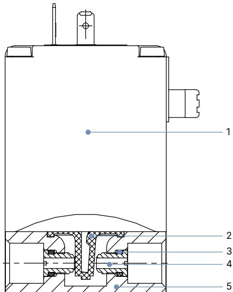
| Item Number | Component | Material |
|---|---|---|
| 1 | Solenoid Coil | Chemically resistant molded epoxy (Class H insulation) |
| 2 | Separating Diaphragm | FKM fluor rubber (Shore hardness 70) |
| 3 | O-Ring External Seal | FKM fluor rubber |
| 4 | Valve Seat | Stainless steel (1.4401) |
| 5 | Valve Body | Stainless steel (1.4401) |
Because all wetted components consist exclusively of 1.4401 stainless steel and FKM elastomer, BURKERT 20000714 resists oxidizing acids, oils with additives, industrial salt solutions, technical oxygen, and neutral process water.
BURKERT 20000714 operates in Circuit Function A (2/2-way direct-acting valve, closed in de-energized position). Flow direction is determined by the internal valve seat geometry with flow directed above the seat.
| Circuit Function | Connection 1 (Inlet) | Connection 2 (Outlet) | Connection 3 |
|---|---|---|---|
| CF A (2/2-way NC) | Port P (Pressure inlet) | Port A (Working outlet) | Not present (closed body) |
In de-energized rest state, the spring-loaded pivoted armature presses the FKM diaphragm against the stainless steel seat, sealing port P. Upon applying 120 V AC 60 Hz power to the coil terminals, the armature tilts upward, opening the path between port 1 (P) and port 2 (A).
The metal housing features female threaded NPT 1/4 fluid ports with an installation face-to-face length of 46 mm.
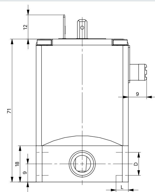
| Thread Designation | Thread Code | Diameter D2 | Minimum Thread Depth L2 |
|---|---|---|---|
| NPT 1/4 | NPT 1/4 | 1/4" | 7.5 mm |
The unit is secured to mounting plates, manifold brackets, or machine frames via two M4 threaded holes located on the bottom face of the stainless steel body:
Installation orientation is unrestricted; positioning the actuator upright with the coil on top is recommended by the manufacturer to minimize sediment deposition around the diaphragm perimeter.
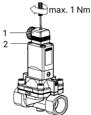
Type 0330 includes a service-friendly manual override located on the upper section of the valve housing for commissioning, dry testing, and emergency override without electrical actuation.

Manual Override Interlock
When the manual override is mechanically locked in the actuated state, the valve cannot be closed or controlled electrically. Ensure the override is unlocked before returning the line to automated operation. To protect against unintended actuation, an optional external circlip (Part No. 013372) can be fitted.
Prior to screwing the valve into the pipe network, pipelines must be thoroughly flushed to eliminate metal shavings, thread burrs, and particulate contamination.
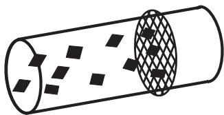
Upstream Filtration Requirement
For dependable long-term shut-off and seal protection, install a dirt trap or inline strainer with a mesh rating of ≤ 500 µm directly upstream of the valve inlet (Port P).
BURKERT 20000714 features a plug connection interface conforming to DIN EN 175301-803 Form A (formerly DIN 43650). The mating cable plug is not included in standard delivery and must be specified separately.
Functional Safety Notice
During extended downtime, at least 1 to 2 switching test cycles are recommended prior to restart to confirm free movement of the pivoted armature.
| Accessory Description | Specification / Circuit Function | Article Number |
|---|---|---|
| Cable Plug Type 2518 Form A | Without wiring (0...250 V AC/DC) | 314802 |
| Cable Plug Type 2518 Form A | With LED indicator (12...24 V AC/DC) | 314812 |
| Cable Plug Type 2518 Form A | With LED indicator and varistor (12...24 V AC/DC) | 314820 |
| Cable Plug Type 2518 Form A | With bridge rectifier, LED, and varistor (12...24 V AC/DC) | 314816 |
| Cable Plug Type 2509 Form A | Standard industrial plug without wiring (0...250 V AC/DC) | 137943 |
| Mounting Plate Kit | Complete assembly for 35 mm DIN rail mounting (2/2-way straight-pass body) | 013253 |
| Locking Circlip | Mechanical lock ring preventing accidental manual override actuation | 013372 |
Explore similar products in our catalog


