
Up to 99.8% Efficiency

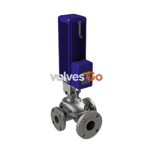
BURKERT 20000987 (Type 3285) is an electromotive 2-way disc control valve with G 3/4 brass body, DN 12 ceramic seat, 3.9 m³/h Kv, 0-6 bar rating, 24 V DC drive, integrated PID process controller, and büS/CANopen interface.
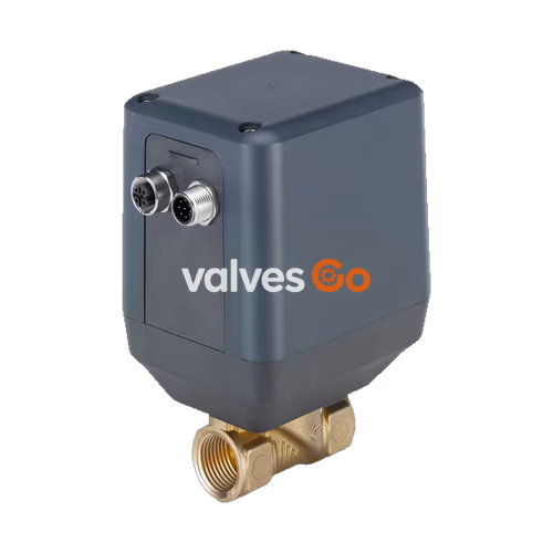
BURKERT 20000987 (Type 3285) is an electromotive direct-acting 2-way disc control valve engineered for dosing and continuous flow regulation of neutral liquids and gases in open or closed control loops. Configured with a G 3/4 female threaded brass body, an orifice seat diameter of 12 mm (DN 12), and technical ceramic discs with NBR sealing, this valve operates over a differential pressure range of 0 to 6 bar(g) and delivers a nominal water flow rate of Kv 3.9 m³/h. Actuation is performed by a 24 V DC stepper motor with integrated digital control electronics, requiring less than 1 W in holding position and up to 12 W during active repositioning.
Article 20000987 belongs to the digital process controller variant (Device variant D), which incorporates an internal cascade control structure. The primary loop runs a software-configurable PID algorithm comparing the external process setpoint against the actual process value received via an auxiliary M12 sensor socket. The subordinate secondary loop regulates physical valve travel via a non-contact displacement sensor with a dead band of ±0.5%, corresponding to a 1:100 setting range. Digital integration is achieved through the büS fieldbus interface (based on CANopen), fully compatible with the Bürkert EDIP platform.
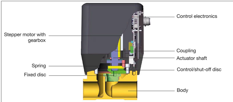
Type 3285 regulates fluid flow through two sliding technical ceramic discs. The stepper motor drives a reduction gearbox that transfers rotational torque via a coupling to the actuator shaft. The actuator shaft is mechanically linked to a movable control and shut-off disc, which is pressed against a fixed ceramic orifice disc by a supporting spring. The motor rotates the upper ceramic disc over a travel angle of approximately 180° across the fixed port opening to adjust or close the flow orifice.
Key functional characteristics of Type 3285 include:
| Specification Parameter | Value / Technical Rating |
|---|---|
| Product Identity | BURKERT Type 3285 (Article 20000987) |
| Valve Construction | 2-way electromotive disc control valve |
| Fluidic Connection | G 3/4 internal thread (EN ISO 228-1) |
| Orifice Size (Seat Diameter) | 12 mm (DN 12, 7/16") |
| Flow Capacity (Kv water at +20 °C, Δp 1 bar) | 3.9 m³/h |
| Operating Pressure Range | 0 to 6 bar(g) |
| Closing Time (0 to 100% Stroke) | approx. 4 s (normal speed) |
| Position Control Dead Band | ±0.5% (corresponds to 1:100 setting range) |
| Operating Voltage | 24 V DC ±10% (max. residual ripple 10%) |
| Power Consumption | Standby holding: < 1 W; Actuation: max. 12 W |
| Operating Media | Neutral gases and liquids |
| Viscosity Limit | max. 80 mm²/s (cSt) |
| Medium Temperature Range | 0 °C to +70 °C (NBR / FKM seals) |
| Ambient Temperature Range | -10 °C to +60 °C (subject to derating) |
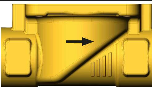
| Flow Direction | Over seat (flow direction above seat) |
| Enclosure Rating | IP50 |
| Device Weight | approx. 1.2 kg (DN 12/15 VA body baseline) |
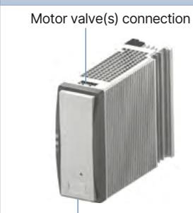
In the process controller configuration (Device variant D), Type 3285 functions as a self-contained cascade control station. The process set-point value (SP) is transmitted digitally via büS/CANopen or configured internally. The actual process variable (PV)—such as flow, pressure, temperature, or conductivity—is fed into the secondary 5-pin M12 circular socket from an external transmitter.
The integrated PID algorithm computes a position setpoint (CMD) based on the calculated control deviation (Xd1). The subordinate positioner loop measures the current physical actuator position (POS) using the internal non-contact sensor, derives the internal positional control difference (Xd2), and modulates the motor drive control variable (CTRL) to adjust the ceramic disc opening angle.
Supported process actual value signals (socket M12, 5-pin):
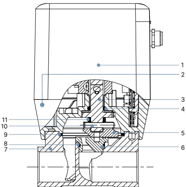
| Item No. | Component Part | Material Specification |
|---|---|---|
| 1 | Housing Cover | Polycarbonate (PC GF10) |
| 2 | Housing Base | Polyphenylene sulphide (PPS GF40) |
| 3 | Spindle | Stainless steel 1.4404 / 1.4401 (316L / 316) |
| 4 | Spindle Seal | NBR (optional FKM or EPDM) |
| 5 | Control Disc | Technical oxide ceramics |
| 6 | Valve Fixed Seat | Technical oxide ceramics |
| 7 | Valve Body | Brass (Article 20000987); optional stainless steel 1.4408 |
| 8 | O-ring | NBR (optional FKM or EPDM) |
| 9 | O-ring | NBR (optional FKM or EPDM) |
| 10 | Parallel Pin | Stainless steel 1.4401 |
| 11 | Supporting Spring | Spring steel / Stainless steel |
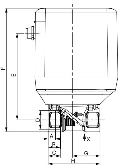
All dimensions in the following table are given in millimeters (mm):
| Thread Standard | Size | A (NPT) | B (NPT/RC) | C (G) | D (Port) | E | F | G | H |
|---|---|---|---|---|---|---|---|---|---|
| NPT / RC / G | 1/2 | 8.2 | 13.7 | 14.0 | 1/2" | 97.0 | 138.0 | 31.0 | 58.0 |
| NPT / RC / G | 3/4 (20000987) | 8.6 | 14.0 | 16.0 | G 3/4" | 103.5 | 147.0 | 43.0 | 80.0 |
| NPT / RC / G | 1 | 10.2 | 16.8 | 18.0 | 1" | 108.5 | 156.5 | 49.0 | 95.0 |
For article 20000987, the port thread is G 3/4 (parallel female thread according to EN ISO 228-1). The body length H is 80.0 mm, thread engagement depth C is 16.0 mm, centerline-to-port dimension G is 43.0 mm, overall width E is 103.5 mm, and total assembly height F is 147.0 mm.
Article 20000987 features two M12 circular connectors located on the actuator housing: a 5-pin M12 A-coded male plug for power supply and digital fieldbus communication, and a 5-pin M12 A-coded female socket for external process actual value transmitter signals.
| Pin | Wire Color (büS Cable) | Configuration | External Circuit / Signal Details |
|---|---|---|---|
| 1 | Bare | Shielding | Connected to valve body / ground |
| 2 | Red | Supply + | 24 V DC ±10% (max. residual ripple 10%) |
| 3 | Black | GND | 24 V DC Power Supply GND |
| 4 | White | CAN high | CANopen / büS dominant high |
| 5 | Blue | CAN low | CANopen / büS dominant low |
| Pin | Wire Color (Cable 559177) | Configuration | External Sensor Circuit |
|---|---|---|---|
| 1 | Brown | Sensor supply + | 24 V DC ±10% (max. 100 mA sensor power) |
| 2 | White | Actual value input sensor + | 0/4–20 mA, 0–5/10 V, or Frequency (PNP) |
| 3 | Blue | GND | Sensor GND |
| 4 | Black | GND | GND bridge (internally bridged to Pin 3) |
| 5 | Grey | Not assigned | Leave unconnected |
| Body | - | Shielding | Connected to ground housing |
Grounding and Potential Isolation
None of the electrical inputs and outputs of Type 3285 are galvanically isolated from the supply voltage. The threaded metal sleeve of the M12 connectors is internally bonded to the valve body. Connect the valve body to an appropriate protective earth point using a low-impedance grounding strap to maintain EMC compliance.
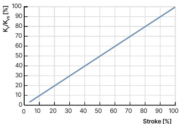
Type 3285 features an inherently linear flow characteristic curve determined by the geometry of the sliding ceramic orifice discs.
| Seat Size (DN) | Standard Port | Kv Value Water [m³/h] | Operating Pressure Range [bar(g)] |
|---|---|---|---|
| 8 | G 1/2 | 1.8 | 0 to 6 |
| 10 | G 1/2 | 2.5 | 0 to 6 |
| 12 (20000987) | G 3/4 | 3.9 | 0 to 6 |
| 15 | G 3/4 | 5.4 | 0 to 6 |
| 20 | G 1 | 8.1 | 0 to 6 |
| 25 | G 1 | 9.6 | 0 to 6 |
Kv values measured with water at +20 °C and 1 bar differential pressure across the fully open valve.
For liquid media: $$K_v = Q \cdot \sqrt{\frac{\rho}{1000 \cdot \Delta p}}$$
For gaseous media under sub-critical expansion ($p_2 > p_1 / 2$): $$K_v = \frac{Q_N}{514} \cdot \sqrt{\frac{T_1 \cdot \rho_N}{p_2 \cdot \Delta p}}$$
For gaseous media under super-critical expansion ($p_2 < p_1 / 2$): $$K_v = \frac{Q_N}{257 \cdot p_1} \cdot \sqrt{T_1 \cdot \rho_N}$$
Where $Q$ is volume flow [m³/h], $Q_N$ is standard flow rate [m³_N/h], $p_1$ is inlet pressure [bar abs], $p_2$ is outlet pressure [bar abs], $\Delta p$ is differential pressure [bar], $\rho$ is liquid density [kg/m³], $\rho_N$ is standard gas density [kg/m³], and $T_1$ is inlet temperature [K].
Seat Sizing Requirement
To prevent the linear characteristic from deteriorating into a non-linear operating curve, ensure that when fully open, the valve absorbs at least 25% of the total system pressure drop: $$\Delta p_{\text{valve}} > 0.25 \cdot \Delta p_{\text{total}}$$ The calculated $K_v$ demand should be roughly 10% below the selected nominal $K_{vs}$ value ($K_{vs} \approx 1.1 \cdot K_v$).
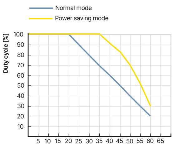
The duty cycle rating refers specifically to the stepper motor operating time, not total powered-on time. The motor energizes only when moving the ceramic disc to a new throttle position. Rapid, continuous setpoint oscillations cause motor self-heating and require adherence to the thermal derating diagram.
Key thermal boundaries:
Type 3285 process controller versions communicate with the Bürkert Communicator software (Type 8920) via büS/CANopen. Connection to a Windows PC requires a USB-büS interface stick set (Type 8923).
Software configuration parameters include:
Fail-Safe Emergency Positioning
 In standard configuration, Type 3285 holds its last physical position during a complete electrical power outage. To enforce an automated fail-safe return, connect an external capacitive buffer module (Type 1573, Article 773440). When supply voltage fails, the buffer module delivers 18 V DC for several seconds, prompting the valve logic to drive the ceramic discs into the pre-configured safety position (factory default: fully closed). Up to two Type 3285 valves can be supported by one buffer module.
| Item Description | Order Code / Article No. |
|---|---|
| Power supply unit Phoenix Class 2 (Type 1573), 85–240 V AC / 24 V DC, 1.25 A, NEC Class 2 | 772438 |
| DIN-rail power supply unit (Type 1573), 100–240 V AC / 24 V DC, 1.0 A, NEC Class 2 | 772361 |
| DIN-rail power supply unit (Type 1573), 100–240 V AC / 24 V DC, 2.0 A, NEC Class 2 | 772362 |
| DIN-rail power supply unit (Type 1573), 100–240 V AC / 24 V DC, 3.8 A, NEC Class 2 | 772898 |
| Capacitive buffer module (Type 1573) for fail-safe emergency position | 773440 |
| M12 shielded sensor cable, 5-pin, length 2.0 m (for process sensor socket) | 559177 |
| M12 circular socket with pre-wired cable, 8-pin, length 2.0 m (analog variant) | 919061 |
| M12 circular socket with pre-wired shielded cable, 8-pin, length 2.0 m (analog variant) | 918991 |
| büS adapter, M12 socket 8-pin to M12 plug 5-pin (for büS stick connection) | 773286 |
| USB-büS interface set 1 (Type 8923): M12/micro-USB cable, büS stick with terminator, power unit | 772426 |
| USB-büS interface set 2 (Type 8923): büS stick, M12 cable, micro-USB cable, Y-distributor (0.7 m) | 772551 |
| Bürkert Communicator PC Software | Type 8920 |
Type 3285 features an integrated multi-color LED display indicating operational and diagnostic states:
| Fault Phenomenon | Possible Root Cause | Remedial Action |
|---|---|---|
| LED unlit | No 24 V DC power supply | Check power supply unit and wiring integrity |
| LED flashing white sporadically | Supply voltage dipping under motor load | Replace with power supply meeting peak 12 W load requirement |
| LED flashing or illuminated red | Residual ripple of DC voltage > 10% | Use regulated DC power supply with smooth filtering |
| LED flashing or illuminated red | Excessive ambient or medium temperature | Reduce ambient heat load; lower duty cycle according to derating curve |
| LED flashing or illuminated red | Sensor signal input < 4 mA or cable break | Inspect sensor cable and wiring connections |
| LED flashing or illuminated red | büS/CANopen communication timeout | Check fieldbus line continuity, terminating resistors, and baud rate |
| Zero flow rate despite open command | Setpoint within cutoff dead band | Verify setpoint exceeds configured cutoff limit (> 1%) |
| Valve does not open or close fully | Low power function activated under high Δp | Deactivate low power mode if differential pressure exceeds 1 bar |
| Internal leakage in closed position | Debris trapped between ceramic discs | Flush pipework, inspect upstream filter, or service ceramic seat |
Explore similar products in our catalog