

PN16

BURKERT 20008302 (Type 6281) is a 2/2-way servo-assisted NC solenoid valve with brass body, G 1/2 port, EPDM seals, and 24V DC coil. Operating pressure 0.2-16 bar, Kv 3.8 m3/h.
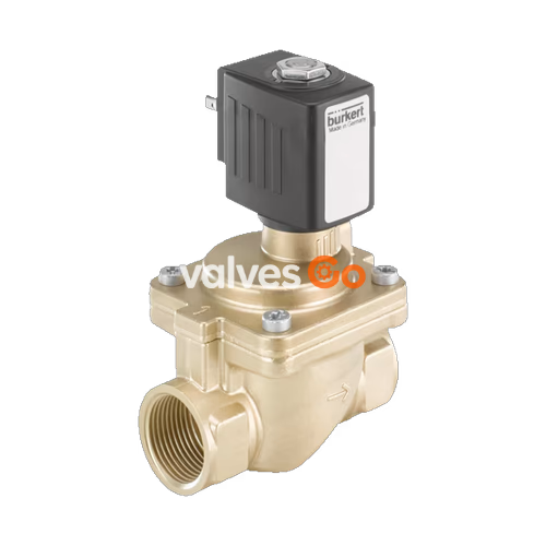
BURKERT 20008302 (Type 6281 EV) is a servo-assisted 2/2-way diaphragm solenoid valve configured in circuit function A (normally closed, inlet port 1 / P). Designed with a nominal orifice of DN 13 mm (pilot orifice 1.2 mm) and female G 1/2 process ports, the unit handles neutral liquids and gases within a pressure range of 0.2 to 16 bar. Media-contacting components combine a brass body conforming to DIN EN 50930-6 with ethylene-propylene-diene rubber (EPDM) seals. Powered by a 24 V DC solenoid rated for 100% continuous duty, the valve achieves a water flow factor (Kv) of 3.8 m³/h and a gas flow rate (QNn) of 4,100 l/min.
The servo-assisted diaphragm architecture requires a minimum differential pressure of 0.2 bar for opening, while opening the complete cross-section requires a pressure differential of 0.5 bar. When de-energized, the core spring presses the pilot seal against the pilot orifice, causing pressure to build above the diaphragm through a small equalization channel and keeping the valve tightly closed over the seat. Energizing the 24 V DC coil lifts the plunger to unseat the pilot channel, venting the chamber above the diaphragm to the outlet and allowing upstream medium pressure to lift the diaphragm for damped, low-noise opening.
| Parameter | Specification |
|---|---|
| Product Type | Type 6281 (Generation EV) |
| Article Number (SKU) | 20008302 |
| Circuit Function | A (2/2-way, normally closed) |
| Nominal Diameter (DN) | 13 mm (pilot orifice 1.2 mm) |
| Port Connection | Internal thread G 1/2 (DIN ISO 228) |
| Operating Voltage | 24 V DC (voltage tolerance ±10%) |
| Solenoid Power Consumption | Cold power: 9.5 W, warm power: 8 W |
| Operating Pressure Range | 0.2 to 16 bar (nominal pressure PN 16) |
| Minimum Differential Pressure | 0.2 bar (0.5 bar for full opening) |
| Flow Capacity Kv (Water) | 3.8 m³/h (measured at +20 °C, 1 bar delta P) |
| Flow Capacity QNn (Gas) | 4,100 l/min |
| Body Material | Brass acc. to DIN EN 50930-6 |
| Sealing Material | EPDM (seat seal and external O-rings) |
| Medium Temperature | -30 °C to +100 °C |
| Ambient Temperature | -30 °C to +55 °C |
| Storage Temperature | -40 °C to +80 °C |
| Permissible Fluid Viscosity | Up to 21 mm²/s |
| Switching Times | Opening: 0.1 to 1.5 s, closing: 0.2 to 4 s |
| Duty Cycle | 100% continuous operation (ED) |
| Degree of Protection | IP65 (with cable plug assembled) |
| Electrical Connection | Plug pattern Form A acc. to DIN EN 175301-803 |
| Flow Direction | Over seat (marked by directional arrow on body) |
| Installation Length | 65 mm |
| Approvals & Conformities | UL Listed, cURus Recognized (UL 429), CE, EAC |
Medium Compatibility with EPDM Seals
Valves fitted with EPDM seals are suitable for cold and hot water, and oil-free and fat-free liquids. Per source documentation, EPDM must not be used with media containing mineral oils, petrol, or hydrocarbons.
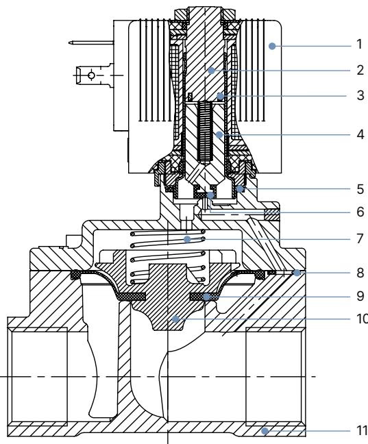
| Item | Component | Material |
|---|---|---|
| 1 | Solenoid coil | Polyamide (PA, thermal insulation class B) |
| 2 | Stopper | Stainless steel 1.4113 |
| 3 | Shading ring | Copper (brass body version) |
| 4 | Magnetic core (plunger) | Stainless steel 1.4113 |
| 5 | O-ring | EPDM |
| 6 | Core seal | EPDM |
| 7 | Core spring | Stainless steel 1.4310 |
| 8 | O-ring | EPDM |
| 9 | Diaphragm | EPDM |
| 10 | Diaphragm holder | Poly Phenylene Sulfide (PPS GF40) |
| 11 | Valve body | Brass acc. to DIN EN 50930-6 |
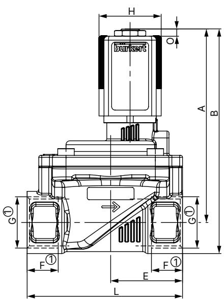
Dimensions below correspond to standard threaded valve variants in millimeters (mm):
| Dimension Parameter | DN 10 (G 1/4, G 3/8) | DN 10 (G 1/2) | DN 13 (G 1/2 — Article 20008302) | DN 13 (G 3/4) | DN 20 (G 3/4) | DN 25 (G 1) |
|---|---|---|---|---|---|---|
| Height A | 83.1 | 85.1 | 91.1 | 93.1 | 99.6 | 106.6 |
| Height B | 94.1 | 98.6 | 104.6 | 109.1 | 115.6 | 127.1 |
| Width C | 32 | 32 | 42 | 42 | 60 | 70 |
| Width D | 44 | 44 | 54.5 | 54.5 | 74 | 85 |
| Centerline E | 22 | 24.5 | 32.5 | 32.5 | 37 | 46 |
| Thread Depth F1 | 12 | 14 | 14 | 16 | 16 | 18 |
| Port Thread G1 | G 1/4, G 3/8 | G 1/2 | G 1/2 | G 3/4 | G 3/4 | G 1 |
| Face-to-Face L | 50 | 50 | 65 | 65 | 80 | 95 |
| Wrench Flat SW | 22 | 27 | 27 | 32 | 32 | 41 |
Mechanical Piping and Depressurization Notice
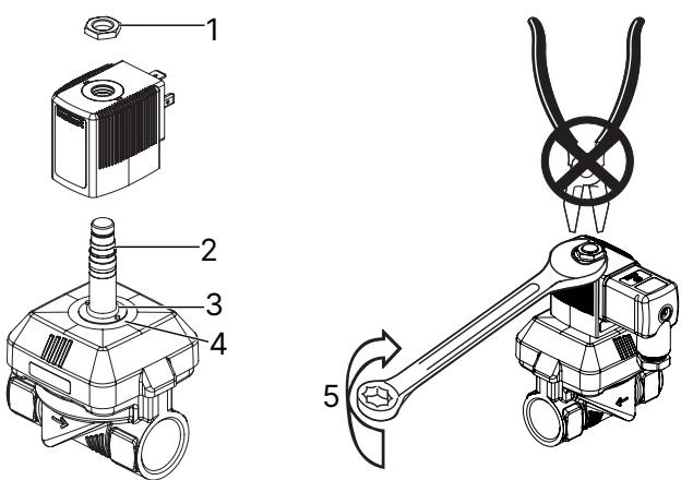
Fire Hazard from Unmounted Coils
Never energize the solenoid coil unless it is fully installed on the valve armature tube. Operating a detached solenoid causes rapid overheating and coil destruction.
Continuous Operation Guidance
To maintain functional reliability during extended plant downtime, perform at least 1 to 2 switching actuations per day.
| Symptom | Probable Cause | Corrective Action |
|---|---|---|
| Valve fails to actuate | Electrical supply interrupted or short circuit | Check terminal voltage, polarity, and coil resistance. |
| Operating pressure out of specification | Verify supply pressure meets the 0.2 to 16 bar range and minimum differential pressure is ≥ 0.2 bar. | |
| Plunger core or core guide chamber contaminated | Disassemble coil and core tube; clean internal core guide and plunger spring assembly. | |
| Valve fails to close | Diaphragm equalization control bore blocked | Remove body screws, inspect diaphragm, and clear the pilot control bore. |
| Internal seat or diaphragm contaminated or damaged | Inspect EPDM diaphragm and valve seat for foreign particulates or wear; replace with genuine spare parts. |
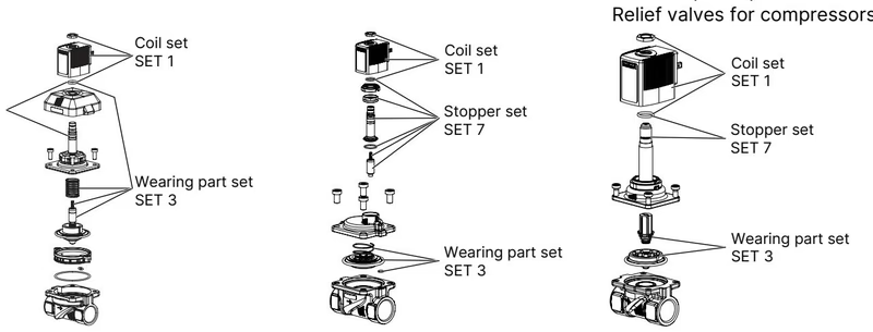
Spare parts for Type 6281 are ordered as structured service sets by quoting the set designation and the device article number (20008302):
Explore similar products in our catalog


