

PN16

Burkert 20009141 Type 8652 AirLINE 12-slot valve island features 12x 2x3/2-way CF-C valves, Industrial Ethernet RJ45, aluminium AirLINE Quick adapter plate, check valves in R/S, and pneumatic HotSwap.
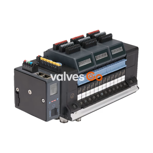
BURKERT 20009141 Type 8652 AirLINE is an electropneumatic 12-slot valve island configured for process automation applications, equipped with twelve 2x 3/2-way normally closed solenoid valves (circuit function C) and mounted on an anodized aluminium AirLINE Quick adapter plate. The unit integrates an ME43 fieldbus gateway delivering multiprotocol Industrial Ethernet connectivity (PROFINET IO, EtherNet/IP, Modbus TCP, EtherCAT, and CC-Link IE Field Basic) via dual RJ45 ports. Operating with an internal auxiliary pilot air supply, the manifold handles operating pressures from -1.00 bar to 10.00 bar and pilot pressures from 3.00 bar to 10.00 bar.
Process safety and system availability are maintained through factory-integrated hardware features: integrated check valves in exhaust ducts 3 (R) and 5 (S) prevent backpressure pulses from triggering inadvertent valve movements, while an integrated pneumatic HotSwap shut-off in channel 1 (P) enables online valve replacement under pressure. Each valve station occupies an 11 mm slice width, providing a nominal flow rate of 310 l/min (with approximately 3% reduction during HotSwap operation). An integrated LC display visualizes detailed status and diagnostic information in plain text and symbols directly at the device.

| Specification Parameter | Technical Value |
|---|---|
| Valve Island Type | 8652 AirLINE |
| Article Number | 20009141 |
| Number of Valve Slots | 12 slots (12 PCE) |
| Configured Valve Slices | 12x 2x 3/2-way CF-C (normally closed) |
| Width per Station | 11 mm |
| Manifold Body Material | PA (Polyamide) |
| Seal Materials | NBR and PUR |
| AirLINE Quick Adapter Material | Anodised aluminium |
| Connection Materials | Nickel-plated brass (supply and working ports) |
| Operating Pressure Range | -1.00 bar to 10.00 bar (vacuum to 10 bar) |
| Auxiliary Pilot Air Pressure | 3.00 bar to 10.00 bar (internal feed) |
| Nominal Flow Rate QNn (Air) | 310 l/min (measured at +20 °C, 6 bar inlet, 1 bar differential) |
| Flow Rate with HotSwap | Approx. 3% flow reduction |
| Operating Voltage | 24 V DC (±10%, residual ripple 1 Vss) |
| Nominal Power per Valve | 0.7 W (0.175 W after electronic power reduction) |
| Nominal Current per Valve | 29 mA (10 mA after electronic power reduction) |
| Duty Cycle | 100% ED (Continuous operation) |
| Valve Switching Time | Opening: 15 ms, Closing: 15 ms (ISO 12238) |
| Medium | Oil-free or lubricated dry compressed air, neutral gases |
| Compressed Air Quality | ISO 8573-1:2010, Class 7.4.4 (5 μm filtration recommended) |
| Degree of Protection | IP20 standalone; IP65 inside closed cabinet via AirLINE Quick |
| Operating Temperature | -10 °C to +55 °C |
| Storage Temperature | -20 °C to +60 °C |
AirLINE Quick enables the valve island to mount directly through cutouts in the control cabinet floor or cabinet wall. This mechanical interface routes pneumatic tubing directly outside the cabinet enclosure, eliminating bulkhead pass-through fittings and significantly reducing required cabinet volume.
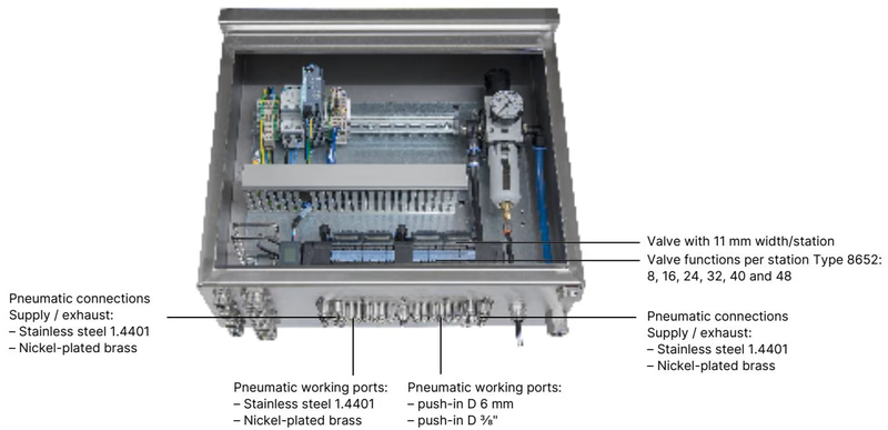
| Feature | AirLINE Quick Specification |
|---|---|
| Adapter Plate Material | Anodised aluminium |
| Pneumatic Supply / Exhaust Ports | Push-in connector D 3/8" (nickel-plated brass) |
| Pneumatic Working Ports | Push-in connector D 1/4" (nickel-plated brass) |
| Installation Position | Control cabinet floor or control cabinet wall |
| Ingress Protection | IP65 achieved inside closed control cabinet |
Article 20009141 is fully populated across all 12 valve slots with 2x 3/2-way solenoid valves with manual override (circuit function C, normally closed). Each valve slice contains two independent servo-assisted 3/2-way pilot stages controlled by Type 6164 pilot operators, controlling two separate working ports per slot (total 24 pneumatic outputs across the manifold).
| Valve Position | Configured Valve Function | Flow Rate QNn | Pressure Range | Response Time | Article No. (Spare Valve) |
|---|---|---|---|---|---|
| Slots 1 through 12 | 2x 3/2-way CF-C (NC) | 310 l/min | Vac. to 10 bar | Open: 15 ms / Close: 15 ms | 301374 (REF 296031) |
Each valve slice features latching/spring-return manual overrides for mechanical commissioning and fault-finding. If replacement is required, individual valves are dismounted via their mounting screws without disassembling the pneumatic baseplate or disconnecting wiring harnesses.
Dimensions for 4-, 8-, and 12-slot configurations follow strict standardized increments based on the 11 mm station pitch.
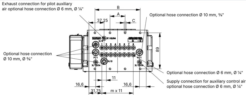
| Variant | Dimension A | Dimension B | Mounting Screws C | Pitch Index m | Spacing Index n |
|---|---|---|---|---|---|
| 4-fold | 66 mm | — | 4× M5 | 3 | 1 |
| 8-fold | 35 mm | 111 mm | 8× M5 | 7 | 2 |
| 12-fold (20009141) | 77 mm | 154 mm | 10× M5 | 11 | 3 |
Mounting screws for securing the AirLINE Quick adapter plate to the control cabinet base utilize M5×10 A2 DIN 6912 fasteners. Standard rail EN 50022 (35 × 7.5 mm or 35 × 15 mm) mounting is also supported.
Electrical power and communication are decoupled into dedicated terminal interfaces to prevent electrical interference and maintain bus operation during valve maintenance.
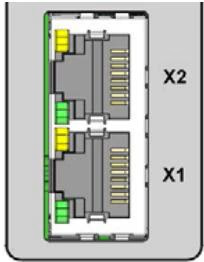
The ME43 gateway provides two switched RJ45 ports supporting linear, star, and ring network topologies across PROFINET IO, EtherNet/IP, Modbus TCP, EtherCAT, and CC-Link IE Field Basic:
| RJ45 Pin | Signal Assignment |
|---|---|
| Pin 1 | TX+ (Transmit Data +) |
| Pin 2 | TX- (Transmit Data -) |
| Pin 3 | RX+ (Receive Data +) |
| Pin 4 | Not connected (N.C.) |
| Pin 5 | Not connected (N.C.) |
| Pin 6 | RX- (Receive Data -) |
| Pin 7 | Not connected (N.C.) |
| Pin 8 | Not connected (N.C.) |
| Interface | Terminal Type | Pin | Conductor Cross-Section | Signal Assignment |
|---|---|---|---|---|
| Communication & Display | 5-pin spring-loaded | 1 (Red) 2 (White) 3 (Green) 4 (Blue) 5 (Black) | ≤ 1.5 mm² | +24 V DC CAN_H (büS) Shielding CAN_L (büS) GND (0 V DC) |
| Pneumatic Valves Power | 2-pin spring-loaded | 1 (Red) 2 (Black) | ≤ 1.5 mm² | AUX +24 V DC GND (0 V DC) |
To ensure unimpeded operation of the pneumatic HotSwap mechanism, mounting positions inside control cabinets must respect minimum clearance boundaries relative to the cabinet front edge and adjacent components.
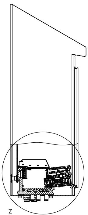
When replacing a valve under pressure, the mechanical latch releases the valve body upwards and outwards. Inadequate clearance to the cabinet door or wiring ducts prevents complete disengagement of the internal shut-off pin. Maintain free vertical and frontal access across the entire 12-slot width.
Article 20009141 incorporates a standard 24 V interface plate without modular shutdown (SIA) circuitry and does not include digital input (DI) modules. All 12 valve stations operate directly from the primary industrial Ethernet fieldbus image.
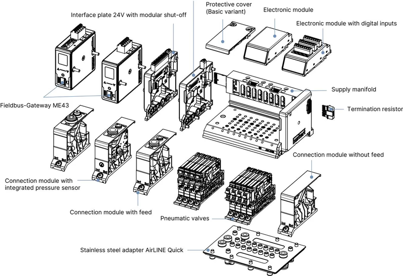
Two internal pneumatic safety mechanisms safeguard connected process valves:
Type 8652 valve terminals comply with ATEX, IECEx, cURus HazLoc, and CCC standards when installed in certified protective enclosures:
Hazardous Area Operational Restriction
Do not connect, disconnect, or manipulate electrical terminals or valves while the system is energized in an explosive atmosphere. The pneumatic HotSwap function must never be executed in a potentially explosive atmosphere unless the ambient area is verified and certified to be entirely free of flammable gases or combustible dust.
Fieldbus Gateway Commissioning Notice
The integrated ME43 fieldbus gateway is unconfigured upon factory delivery. System device description files must be generated and downloaded using Bürkert Communicator software (Type 8920) prior to operational plant startup.
| Item Description | Quantity | Article Number |
|---|---|---|
| Replacement Solenoid Valve Type 6534 (2x 3/2-way CF-C, 24 V DC, with screws) | 1 | 301374 |
| Replacement Solenoid Valve Spare Part Set (REF 296031) | 1 | 296031 |
| Fieldbus Gateway Module Type ME43 (Industrial Ethernet) | 1 | 301799 |
| AirLINE Quick Height Adapter (12-valve base, without intermediate feed) | 1 | 754961 |
| AirLINE Quick Retaining Plate (12-valve base, external cabinet mounting) | 1 | 60005567 |
| AirLINE Quick Blind Plate (12-valve cutout) | 1 | 754966 |
| Screw Set M5×10 A2 DIN 6912 (Cabinet base mounting) | 10 pcs | 308661 |
| 5-Pin Spring-Loaded Terminal (Communication & Display power) | 1 | 920180 |
| 2-Pin Spring-Loaded Terminal (Pneumatic valve power AUX 24 V) | 1 | 920442 |
| USB büS Interface Set 1 Type 8923 (Bürkert Communicator connection kit) | 1 | 772426 |
Explore similar products in our catalog


