

PN16

BURKERT 20012658 (Type 8652) 12-slot AirLINE Quick valve island features Industrial Ethernet communication, 12 dual 3/2-way CF-C valves, D3/8 supply, D1/4 ports, and aluminium adapter plate for cabinet mounting.
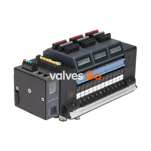
BURKERT 20012658 (Type 8652) is a 12-slot AirLINE Quick valve island configured for process automation applications. Each of the 12 valve positions is factory-equipped with a dual 3/2-way normally closed solenoid valve (Circuit Function C), providing 24 independently controllable pilot channels. The assembly incorporates an Industrial Ethernet communication gateway supporting PROFINET IO, EtherNet/IP, Modbus TCP, EtherCAT, and CC-Link IE Field Basic via two RJ45 female connectors. Pneumatic connections are established through an anodised aluminium AirLINE Quick base plate, featuring brass D 3/8" supply connections and brass D 1/4" working ports, with an integrated internal auxiliary pilot air supply.
The system operates across a process pressure range from -1.0 bar to 10.0 bar (vacuum to 10 bar) and requires an internal pilot air pressure between 3 bar and 10 bar. It includes an integrated LC display that presents diagnostic messages and valve status in clear text and standardized symbols. When installed directly on a control cabinet floor or wall using the AirLINE Quick adapter plate, the pneumatic exhaust and working ports discharge through the cabinet cutout, sealing the interior to IP65 while maintaining an IP20 rating on the terminal body.
| Parameter | Specification |
|---|---|
| Type / Article Number | Type 8652 / Article no. 20012658 |
| Number of Valve Slots | 12 slots (accommodates up to 24 valve functions) |
| Pre-installed Valve Slices | 12x 2x 3/2-way CF-C (normally closed, servo-assisted) |
| Width per Valve Station | 11 mm |
| Body / Seal Materials | PA (polyamide) / NBR and PUR |
| AirLINE Quick Plate Material | Anodised aluminium (working connections: nickel-plated brass) |
| Supply Port / Working Port Size | D 3/8" push-in / D 1/4" push-in (brass) |
| Auxiliary Pilot Air Supply | Internal supply (3 bar to 10 bar required) |
| Working Pressure Range | -1.0 bar to 10.0 bar (vacuum to 10 bar) |
| Nominal Flow Rate $Q_{\text{Nn}}$ (Air) | 310 l/min (measured at +20 °C, 6 bar inlet, 1 bar $\Delta P$) |
| Operating Voltage | 24 V DC ($\pm 10%$, residual ripple 1 Vss) |
| Power per Valve Slice | 0.7 W nominal (0.175 W after electronic power reduction) |
| Current per Valve Slice | 29 mA nominal (10 mA after power reduction) |
| Duty Cycle | 100% continuous operation (ED) |
| Electrical Protection Class | Class III according to DIN EN 61140, VDE 0140 |
| Operating Medium | Oil-free or lubricated compressed dry air, neutral gases (5 µm filtration recommended) |
| Compressed Air Quality | ISO 8573-1:2010, Class 7.4.4 |
| Ambient & Medium Temperature | -10 °C to +55 °C (storage temperature: -20 °C to +60 °C) |
| Ingress Protection Rating | IP20 bare terminal; IP65 inside closed cabinet with AirLINE Quick |
| Explosion Protection (Optional) | ATEX: II 3G Ex ec IIC Gc / II 3D Ex tc IIIC Dc (BVS 20 ATEX E 031 U); IECEx BVS 20.0024 U |
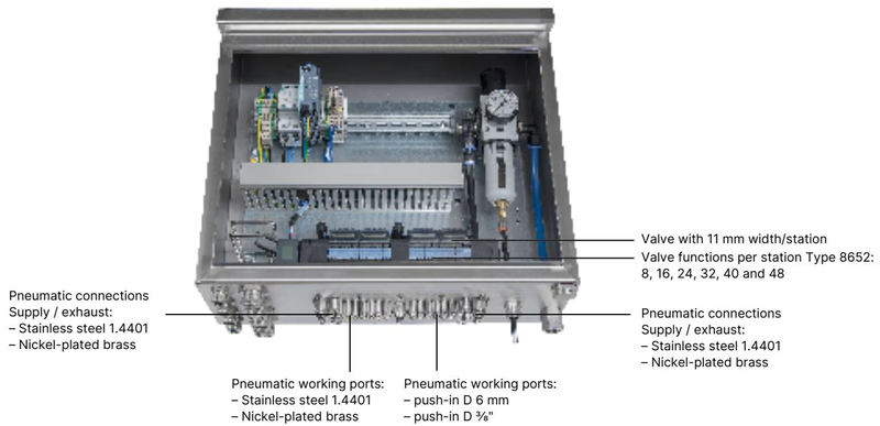
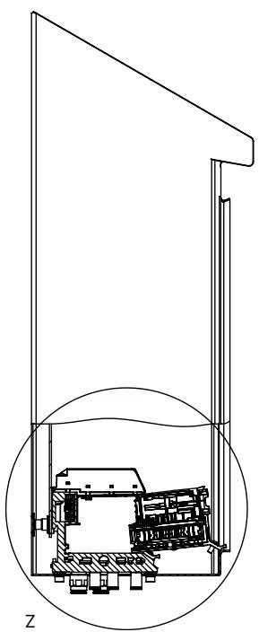
The AirLINE Quick adapter plate integrates the mechanical valve terminal base directly with the control cabinet floor or wall cutout. Tubing connects directly from the exterior baseplate, eliminating bulkhead fittings, internal tubing runs, and intermediate terminal strips inside the enclosure.
Key installation dimensions for the 4-, 8-, and 12-slot configurations are specified below:
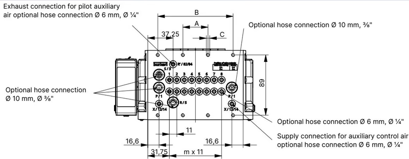
| Configuration | A (mm) | B (mm) | C (Fastening) | m | n |
|---|---|---|---|---|---|
| 4-slot | 66 | — | 4× M5 | 3 | 1 |
| 8-slot | 35 | 111 | 8× M5 | 7 | 2 |
| 12-slot (20012658) | 77 | 154 | 10× M5 | 11 | 3 |
Mechanical Clearances for Hot Swap
When installing the valve island inside a control cabinet, maintain the required front clearance to allow removal and insertion of individual valve slices under pressure. Review the control cabinet front-edge and rear-wall spacing rules documented in the Type 8652 operating instructions.
Article 20012658 is assembled with 12 valve slices of Circuit Function C (2x 3/2-way normally closed). The Type 8652 modular platform also accommodates alternative valve slice configurations using 11 mm Type 6534 pilot valves:
| Circuit Function | Symbol Code | Description | Standard Flow Rate $Q_{\text{Nn}}$ | Switching Time (Open / Close) |
|---|---|---|---|---|
| 2x 3/2-way NC (Configured) | CF C | Dual 3/2-way solenoid valve, servo-assisted, normally closed | 270 l/min | 15 ms / 15 ms |
| Single 3/2-way NC | CF C | 3/2-way solenoid valve, servo-assisted, normally closed | 270 l/min | 15 ms / 15 ms |
| 2x 3/2-way NO | CF D | Dual 3/2-way solenoid valve, servo-assisted, normally open | 310 l/min | 15 ms / 15 ms |
| 5/2-way monostable | CF H | 5/2-way solenoid valve, servo-assisted | 290 l/min | 20 ms / 25 ms |
| 5/2-way bistable | CF Z | 5/2-way impulse solenoid valve, 2 coils | 290 l/min | 20 ms / 25 ms |
| 5/3-way closed | CF L | 5/3-way solenoid valve, middle position closed | 275 l/min | 15 ms / 15 ms |
| 5/3-way ventilated | CF M | 5/3-way solenoid valve, middle position ports 2 & 4 pressurized | 300 l/min | 20 ms / 20 ms |
| 5/3-way exhausted | CF N | 5/3-way solenoid valve, middle position ports 2 & 4 exhausted | 300 l/min | 20 ms / 20 ms |
Article 20012658 features separate power supplies for the electronic communication unit and the pneumatic valve coils, enabling external safety emergency disconnection without disrupting fieldbus communications.
The pre-installed ME43 gateway provides dual MDI/MDI-X 10/100 Mbps RJ45 ports (X1 and X2) supporting Industrial Ethernet protocols (PROFINET IO, EtherNet/IP, Modbus TCP, EtherCAT, and CC-Link IE Field Basic):
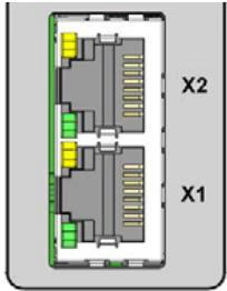
| Pin | Signal | Description |
|---|---|---|
| Pin 1 | TX+ | Transmit Data + |
| Pin 2 | TX- | Transmit Data - |
| Pin 3 | RX+ | Receive Data + |
| Pin 4 | N.C. | Not connected |
| Pin 5 | N.C. | Not connected |
| Pin 6 | RX- | Receive Data - |
| Pin 7 | N.C. | Not connected |
| Pin 8 | N.C. | Not connected |
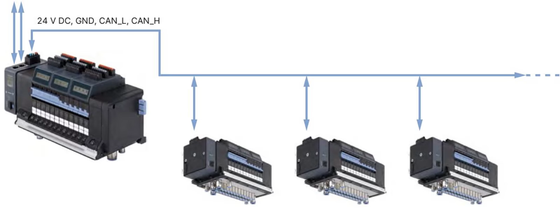
Type 8652 equipped with Industrial Ethernet acts as a primary master valve terminal, transmitting process data and diagnostics to local büS subnet valve terminals:
Gateway Configuration via Bürkert Communicator
Gateway modules Type ME43 are delivered without factory application profiles. Parameter files, protocol selections, and cyclic process data mappings must be generated and loaded using Bürkert Communicator Type 8920 in conjunction with the USB-büS interface set (Article no. 772426).
Operating Rules in Potentially Explosive Atmospheres
For Type 8652 units operating in Zone 2 / 22 environments under ATEX certificate BVS 20 ATEX E 031 U (II 3G Ex ec IIC Gc / II 3D Ex tc IIIC Dc) or IECEx BVS 20.0024 U:
| Valve Model / Function | Pressure Range | Flow Rate $Q_{\text{Nn}}$ | Voltage | Article No. (incl. screws) |
|---|---|---|---|---|
| 2x 3/2-way CF-C (Standard) | Vac. to 10 bar | 270 l/min | 24 V DC | 301374 |
| 2x 3/2-way CF-C (SIA variant) | Vac. to 10 bar | 270 l/min | 24 V DC | 338802 |
| 2x 3/2-way CF-D (Standard) | Vac. to 10 bar | 310 l/min | 24 V DC | 301375 |
| 5/2-way CF-H (Standard) | Vac. to 10 bar | 290 l/min | 24 V DC | 301376 |
| 5/3-way CF-L (Standard) | Vac. to 10 bar | 275 l/min | 24 V DC | 301380 |
| Dummy / Blanking Plate Valve | — | — | — | 335779 |
| Accessory Description | Quantity | Article No. |
|---|---|---|
| Screw set M5×10 A2 DIN 6912 (fastening island to cabinet base) | 10 pcs | 308661 |
| Height adapter plate for 12-slot base (without intermediate feed) | 1 pc | 754961 |
| External retaining plate for 12-slot base (cabinet exterior) | 1 pc | 60005567 |
| Blind cover plate for 12-slot base cutout | 1 pc | 754966 |
| 5-pin spring-loaded terminal (electronics & display power) | 1 pc | 920180 |
| 2-pin spring-loaded terminal (valve coil power) | 1 pc | 920442 |
Explore similar products in our catalog


