

PN16

BURKERT 20013627 Type 8652 is an 8-slot AirLINE valve island with aluminium AirLINE Quick base, 8x CF-N 5/3-way valves, Industrial Ethernet RJ45, HotSwap in 1 (P), and integrated check valves in 3 and 5.
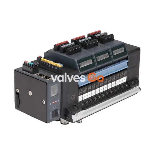
BURKERT 20013627 (Type 8652) is an 8-slot AirLINE pneumatic valve island configured with an anodised aluminium AirLINE Quick adapter plate and an integrated Industrial Ethernet fieldbus module. The unit is pre-assembled with eight 5/3-way servo-controlled solenoid valves operating under circuit function N (middle position exhausted/ventilated). Process connections comprise brass D10 push-in supply fittings and brass D6 push-in working port fittings. Hardware integration includes built-in check valves in exhaust ducts 3 (R) and 5 (S) to suppress backpressure spikes, as well as a pneumatic HotSwap mechanism on port 1 (P) that allows valve replacement during pressurized plant operation.
Type 8652 AirLINE is engineered for process automation environments, featuring an LC display that shows diagnostic data in clear text and graphic symbols. Diagnostic parameters are simultaneously mapped into cyclic and acyclic communication words for PLC-level status evaluation. The valve terminal mounts directly through the floor or wall of a control cabinet using the AirLINE Quick adapter, delivering an IP65 seal to the process environment while maintaining an IP20 rating inside the enclosure.

| Parameter | Specification |
|---|---|
| Body material | PA (polyamide) |
| Seal materials | NBR and PUR |
| Station width | 11 mm per slice |
| Maximum valve slots / functions | Max. 24 slots / max. 48 valve functions (8 slots pre-configured on 20013627) |
| Manual override | Latching, spring return (optional: lockable) |
| Operating pressure range | Vacuum to 10 bar (-1.00 bar to 10.00 bar) |
| Auxiliary pilot air pressure | 3 bar to 10 bar (internal pilot feed) |
| Flow rate $Q_{\text{Nn}}$ (air) | 310 l/min (measured at +20 °C, 6 bar inlet, 1 bar differential pressure); 300 l/min for CF-N |
| HotSwap flow impact | Flow reduced by approx. 3 % with integrated HotSwap valve seat |
| Nominal operating mode | Continuous operation (100 % duty cycle) |
| Switching time measurement | In accordance with ISO 12238 |
| Operating voltage | 24 V DC (±10 %, residual ripple 1 Vss) |
| Nominal power per valve | 0.7 W inrush (0.175 W holding after electronic power reduction) |
| Nominal current per valve | 29 mA (10 mA holding after electronic power reduction) |
| Protection class | III in accordance with DIN EN 61140, VDE 0140 |
| Operating medium | Oil-free or lubricated compressed dry air, neutral gases (5 μm filtration recommended) |
| Compressed air quality | ISO 8573-1:2010, Class 7.4.4 |
| Ambient temperature | -10 °C to +55 °C |
| Storage temperature | -20 °C to +60 °C |
| Mounting position | Any |
AirLINE Quick allows direct bulkhead mounting of the valve terminal onto the control cabinet floor or wall. Pneumatic hose connections are routed through the cabinet boundary, eliminating external pass-through bulkheads and interior tube routing.
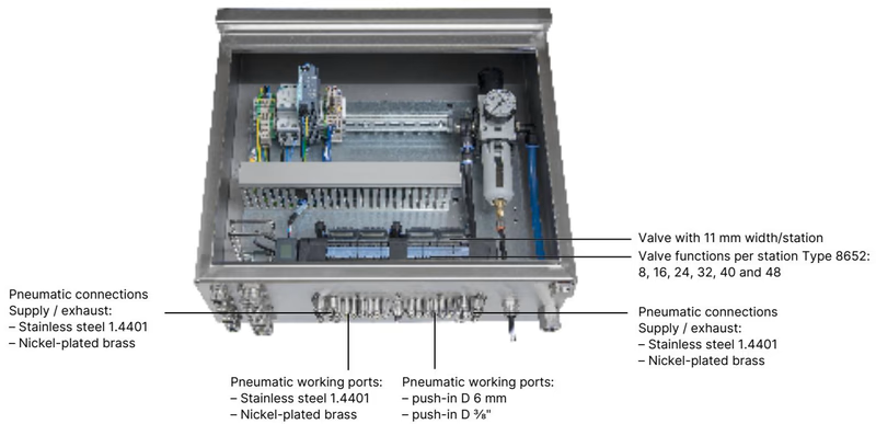
AirLINE Quick Advantages
| Component | Material / Specification |
|---|---|
| AirLINE Quick adapter plate | Anodised aluminium (variant AL) or stainless steel 1.4301 |
| Pneumatic push-in fittings | Nickel-plated brass or stainless steel 1.4401 (brass fitted on 20013627) |
| Supply / exhaust port size | Push-in D10 mm (or 3/8") |
| Working ports size | Push-in D6 mm (or 1/4") |
| Supported station increments | 8, 16, 24, 32, 40, and 48 valve functions |
BURKERT 20013627 is factory-fitted across all eight positions with Circuit Function N (CF-N). The Type 8652 modular platform accommodates several standard and safety-related shut-off (SIA) valve variants using 11 mm wide Type 6534 pilot valves:
| Function Code | Description | Pneumatic Schematic |
|---|---|---|
| CF C | 3/2-way solenoid valve, servo-controlled, normally closed, with manual override | Single valve slice |
| CF C (dual) | 2 × 3/2-way solenoid valve, servo-controlled, normally closed, with manual override | Dual valve slice |
| CF D | 2 × 3/2-way solenoid valve, servo-controlled, normally open, with manual override | Dual valve slice |
| CF H | 5/2-way solenoid valve, servo-controlled, with manual override | Single valve slice |
| CF Z | 5/2-way impulse solenoid valve, 2 coils, with manual override | Bistable valve slice |
| CF L | 5/3-way solenoid valve, servo-controlled, all ports locked in middle position | Middle position closed |
| CF M | 5/3-way solenoid valve, servo-controlled, ports 2 and 4 pressurized in middle position | Middle position ventilated |
| CF N (pre-installed) | 5/3-way solenoid valve, servo-controlled, ports 2 and 4 exhausted in middle position | Middle position exhausted |
| SIA Variants | Circuit functions C, H, and L with dedicated potential-free shutdown terminals | Safety-related shut-off without manual override |
Type 8652 valve islands can be snapped onto standard DIN rail EN 50022 (35 × 7.5 mm or 35 × 15 mm) or mounted via the AirLINE Quick adapter plate on cabinet cutouts.
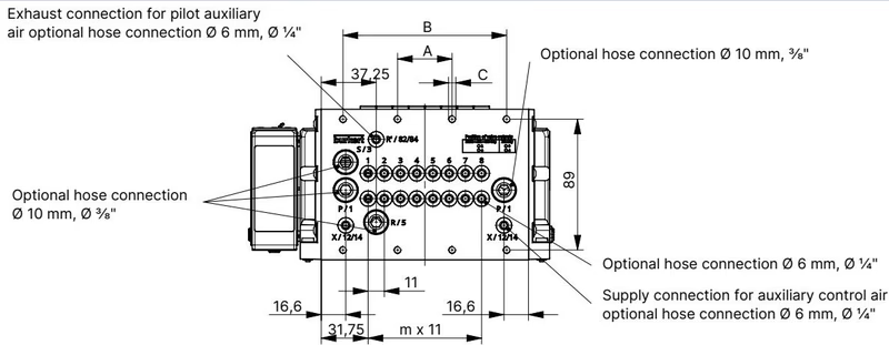
| Variant | Dimension A (mm) | Dimension B (mm) | Fastening Pattern C | Spacing m | Multiplier n |
|---|---|---|---|---|---|
| 4-fold | 66 | — | 4 × M5 | 3 | 1 |
| 8-fold (20013627) | 35 | 111 | 8 × M5 | 7 | 2 |
| 12-fold | 77 | 154 | 10 × M5 | 11 | 3 |
For 16-, 20-, and 24-fold islands, intermediate supply modules are optional. The 8-fold configuration on model 20013627 operates without intermediate feed modules.
Electrical supply is split between logic/bus electronics and the pneumatic solenoid coils to permit independent emergency stopping of valve power without dropping communication.
| Pin | Wire Colour | Assignment |
|---|---|---|
| 1 | Red | 24 V DC (logic supply) |
| 2 | White | CAN_H (büS interface) |
| 3 | Green | Shielding |
| 4 | Blue | CAN_L (büS interface) |
| 5 | Black | 0 V DC (GND) |
Cable cross-section: $\le 1.5\text{ mm}^2$. Compatible with 5-pin plug part number 920180.
| Terminal Clip | Wire Colour | Assignment |
|---|---|---|
| 1 | Red | AUX 24 V (pneumatic valve supply) |
| 2 | Black | 0 V DC (GND) |
Compatible with 2-pin plug part number 920442.
Model 20013627 features dual MII/RMII Ethernet ports supporting multi-protocol Industrial Ethernet: PROFINET IO, EtherNet/IP, Modbus TCP, EtherCAT, and CC-Link IE Field Basic, as well as PROFINET S2 system redundancy.
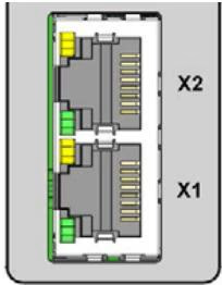
| RJ45 Pin | Signal Assignment |
|---|---|
| Pin 1 | TX+ |
| Pin 2 | TX- |
| Pin 3 | RX+ |
| Pin 4 | Not connected (N.C.) |
| Pin 5 | Not connected (N.C.) |
| Pin 6 | RX- |
| Pin 7 | Not connected (N.C.) |
| Pin 8 | Not connected (N.C.) |
When installing the valve island inside a control cabinet, clearance dimensions to the cabinet door and rear wall must be observed to allow valve replacement while pressurized.
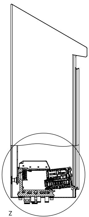
HotSwap Distance Requirements
Maintain adequate spacing between the front of the valve island and the control cabinet door. When removing a Type 6534 valve slice under line pressure, integrated check mechanisms in port 1 seal the supply channel automatically. Ensure the valve can be fully withdrawn vertically without collision with cable ducts or the enclosure frame.
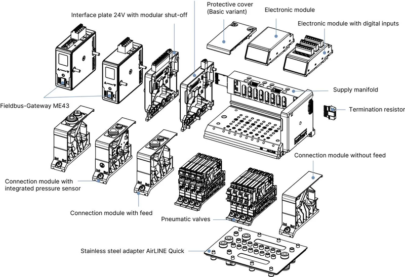
Model 20013627 is delivered with zero digital inputs, but the basic rail can accept optional 8DI electronic modules (part number 384872). The digital inputs supply 24 V DC to connected sensors (limited to 30 mA per channel) and support standard 2-wire sensors, 3-wire sensors, and potential-free mechanical limit switches.
| Parameter | Diagnostic Capability |
|---|---|
| 3-wire sensor | Sensor actuated, sensor unactuated, short-circuit detection |
| 2-wire sensor | Sensor actuated, sensor unactuated, open-circuit (wire break) detection |
| Mechanical switch | Actuated, unactuated |
| Input threshold | $V_{\text{OFF}} = 0\text{ to }5\text{ V}$, $V_{\text{ON}} = 10\text{ to }30\text{ V}$ |
| Input impedance | $>4\text{ k}\Omega$ |
| Maximum cable length | $<30\text{ m}$ (wire gauge $0.14\text{ to }1.5\text{ mm}^2$) |
Safety-instrumented shutdown can be implemented on Type 8652 via two methods:
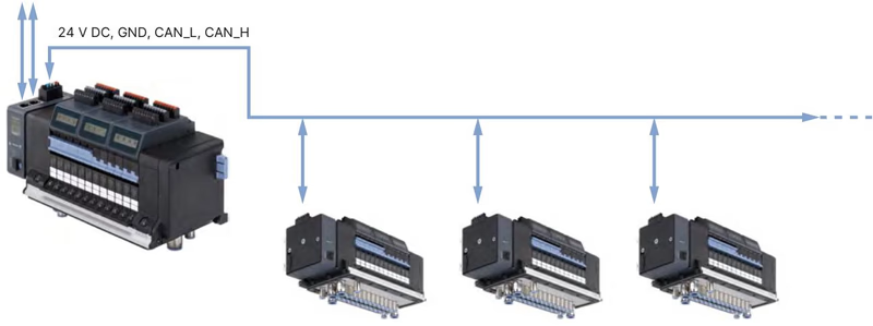
Type 8652 equipped with Industrial Ethernet can act as a master gateway for subordinate büS (CANopen-based) valve islands within the same cabinet or process skid.
Commissioning with Bürkert Communicator (Type 8920)
Initial network configuration, EDIP parameter mapping, and graphic diagnostics require the Bürkert Communicator software and USB büS interface set 1 (article no. 772426). The tool provides cyclic process mapping, acyclic fault logging, and backup/restore of entire valve terminal parameters.
| Function | Circuit Function | $Q_{\text{Nn}}$ Air (l/min) | Pressure Range (bar) | Response Open (ms) | Response Close (ms) | Order Code (incl. screws) |
|---|---|---|---|---|---|---|
| CF C | 3/2-way NC | 270 | Vac. to 10 | 15 | 15 | 20102334 |
| CF C (dual) | 2x 3/2-way NC | 270 | Vac. to 10 | 15 | 15 | 301374 |
| CF D (dual) | 2x 3/2-way NO | 310 | Vac. to 10 | 15 | 15 | 301375 |
| CF H | 5/2-way monostable | 290 | Vac. to 10 | 20 | 25 | 301376 |
| CF Z | 5/2-way bistable | 290 | Vac. to 10 | 20 | 25 | 301377 |
| CF L | 5/3-way locked | 275 | Vac. to 10 | 15 | 15 | 301380 |
| CF M | 5/3-way ventilated | 300 | Vac. to 10 | 20 | 20 | 301379 |
| CF N | 5/3-way exhausted (on 20013627) | 300 | Vac. to 10 | 20 | 20 | 301381 |
| Dummy | Blind plate for unused slot | — | — | — | — | 335779 |
| Description | Quantity | Article No. |
|---|---|---|
| Screw set M5 × 10 A2 DIN 6912 (valve terminal to cabinet base) | 10 pcs | 308661 |
| Height adapter, 8-fold base, without intermediate feed | 1 pc | 754960 |
| Retaining plate, 8-fold base (cabinet exterior mounting) | 1 pc | 60005566 |
| Blind plate, 8-fold base, without intermediate feed | 1 pc | 754965 |
When deployed with explosion-proof options (PX68 or PU17), the following operating limits and conditions apply:
II 3G Ex ec IIC Gc and II 3D Ex tc IIIC Dc.Explore similar products in our catalog


