Type 2032

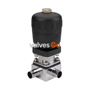
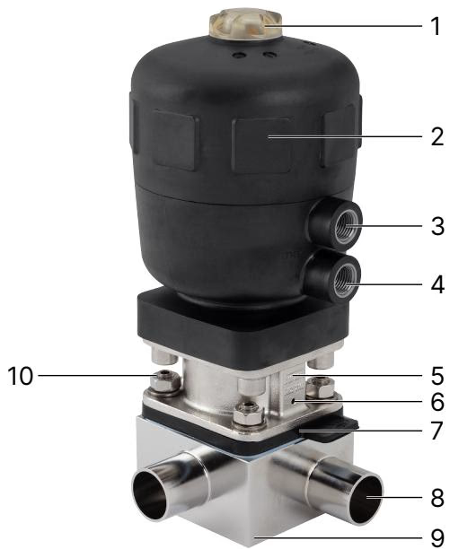
Burkert Type 2032 pneumatic T-diaphragm valve with CLASSIC plastic actuator. Features zero dead volume, autoclavable design, and FDA/3-A approvals for hygienic applications.
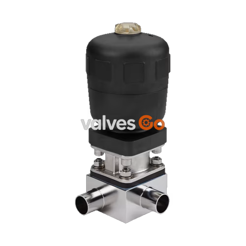
Burkert Type 2032 externally controlled diaphragm valve consists of a pneumatically operated piston actuator, a diaphragm, and a T-valve body. The proven and robust actuator with a plastic housing ensures reliable use in hygienic or aggressive ambient conditions. The flow-efficient valve bodies with little dead space enable high flow rates and a wide range of possible uses. The valve body and the diaphragm are available in all common materials and variants. The actuator features a compact, autoclavable design (PPS variant), making it ideal for sterile applications.
The integration of automation units such as Type 8690/8697 is possible in all configuration levels and can be retrofitted. An explosion-proof ATEX/IECEx device variant is also available. The actuator is equipped with an integrated, optical position indicator as standard, and a minimum/maximum stroke limiter can be installed optionally.
Depending on the control function, spring force (CF A) or pneumatic pilot pressure (CF B, CF I) generates the closing force. A spindle connected to the actuator piston transfers the force to the compressor, which presses the diaphragm against the weir in the valve body.
| Product Properties | Details |
|---|---|
| Block body (VH/VI) | Stainless steel block material 1.4435 according to DIN EN 10088 and 316L according to ASTM A479 / ASME BPE |
| Diaphragm | EPDM (AD), PTFE/EPDM (EA), Advanced PTFE/EPDM (EU), laminate of GYLON® and EPDM (ER) |
| Actuator | PPS, PA |
| Diaphragm size | 8...100 |
| Standard surface quality | Internally electrically polished: Ra ≤ 0.38 μm (ASME BPE SF4 / DIN HE4). Internally mechanically polished: Ra ≤ 0.5 μm (ASME BPE SF1). |
| Maximum pilot pressure | 7 bar (for actuator size 40...125/PPS); 6 bar (for actuator size 175 and 225/PA) |
| Pilot air port | Thread G 1/4, thread G 1/8 for actuator size 40 and 50 |
| Operating medium | Neutral gases and liquids, highly purified, sterile, aggressive or abrasive mediums |
| Control medium | Neutral gases, air |
| Nominal diameter | DN 06...DN 100 (1/8"...4") |
| Diaphragm Material | Medium Temperature | Comments |
|---|---|---|
| EPDM (AD) | -10 °C...+143 °C | Steam sterilisation max. +150 °C for 60 min |
| PTFE/EPDM (EA) | -10 °C...+130 °C | Steam sterilisation max. +140 °C for 60 min |
| Advanced PTFE/EPDM (EU) | -5 °C...+143 °C | Steam sterilisation max. +150 °C for 60 min |
| Laminate of GYLON® and EPDM (ER) | -5 °C...+130 °C | Steam sterilisation max. +140 °C for 60 min |
| Symbol | Description |
|---|---|
| Control function A (CF A) | Pneumatically operated T-valve. Normally closed by spring force. |
| Control function B (CF B) | Pneumatically operated T-valve. Normally opened by spring force. |
| Control function I (CF I) | Pneumatically operated T-valve on either side. Switching position dependent on external control. |
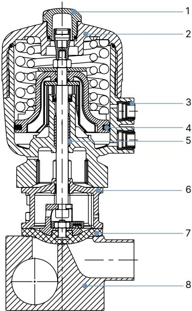
| No. | Element | Material |
|---|---|---|
| 1 | Transparent cap | Polysulfone PSU |
| 2 | Cover | Polyphenylene sulphide PPS (standard), Polyamide PA (on request) |
| 3 | Pilot air ports | Stainless steel 1.4305 |
| 4 | Piston seal | FKM |
| 5 | Socket | Sinter metal |
| 6 | Interface | Stainless steel 1.4404 |
| 7 | Diaphragm | EPDM, PTFE/EPDM, Advanced PTFE/EPDM, laminate of GYLON® and EPDM |
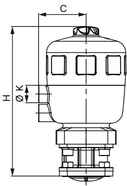
| Diaphragm size | Actuator size ∅ | ∅ A | C | K | H |
|---|---|---|---|---|---|
| 8 | 40 (C) | 53 | 34 | G 1/8" | 111 |
| 15 | 50 (D) | 64 | 39 | G 1/8" | 137 |
| 15 | 63 (E) | 80 | 52 | G 1/4" | 154 |
| 20 | 63 (E) | 80 | 52 | G 1/4" | 165 |
| 20 | 80 (F) | 101 | 52 | G 1/4" | 186 |
| 25 | 63 (E) | 80 | 52 | G 1/4" | 170 |
| 25 | 80 (F) | 101 | 60 | G 1/4" | 190 |
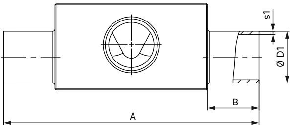
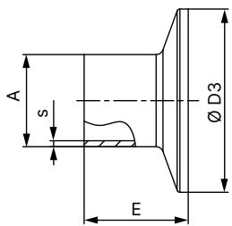
(Dimensions in mm, unless otherwise stated. Please refer to the full datasheet for comprehensive dimensional tables covering all port sizes and standards including DIN EN ISO 1127, ASME BPE, and SMS 3008).
Note
The clamp dimensions must be added to the welded connection dimensions.
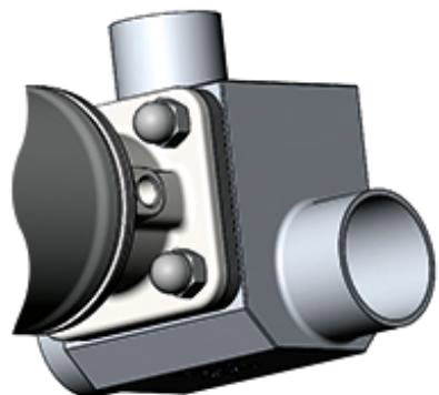
The diaphragm valve can be installed in any position, preferably with the actuator facing up. The following installation positions are recommended for the installation of T-valve bodies in circular pipelines to ensure self-draining capabilities:
Installation for Leakage Detection
One of the relief bores in the diaphragm bonnet for monitoring leakages must be at the lowest position.
| Diaphragm size | Actuator size ∅ | Pilot pressure [bar] | Max operating pressure EPDM, FKM [bar] | Max operating pressure PTFE, GYLON® [bar] |
|---|---|---|---|---|
| 8 | 40 (C) | 5.0...7 | 10 | 10 |
| 15 | 50 (D) | 5.0...7 | 10 | - |
| 15 | 63 (E) | 5.0...7 | 10 | 10 |
| 20 | 63 (E) | 5.5...7 | 10 | 10 |
| 20 | 80 (F) | 5.0...7 | 10 | 10 |
| 25 | 80 (F) | 5.5...7 | 10 | 10 |
| 40 | 100 (G) | 5.5...7 | 10 | 9 |
| 40 | 125 (H) | 5.5...7 | 10 | 10 |
Pressure Limits
For low operating pressures, optional variants with reduced spring force (EC04) are recommended. The maximum operating pressure for laminate of GYLON® and EPDM (ER diaphragm) is 6 bar for size 40/100(G).
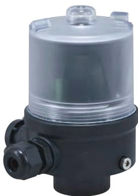
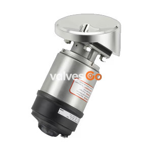
The position feedback Type 8697 is designed for integrated mounting on CLASSIC series 20XX process valves, suiting the requirements of hygienic process environments. Mechanical or inductive limit switches register the position of the valve.
Explore similar products in our catalog