PN16

Burkert 20016143 Type 7011 direct-acting 2/2-way plunger valve. Features a 2.0 mm orifice, G1/8 internal thread, stainless steel body, EPDM seal, and 24V DC operation.
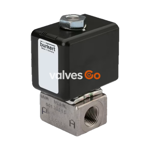
BURKERT 20016143 Type 7011 is a direct-acting and compact 2/2-way plunger valve designed for blocking, dosing, filling, and ventilating neutral gaseous and liquid media. The stopper and the core guide tube are welded together to increase pressure resistance and leak-tightness. This specific model features a 2.0 mm orifice, G1/8 internal thread, stainless steel body, EPDM seal, and operates on 24V DC. It utilizes a slipped-over coil system and provides a simple and fast mounting solution. When used in combination with a plug conforming to DIN EN 175301-803 shape B, the valve satisfies the IP65 degree of protection.
| Product Properties | Specification |
|---|---|
| Orifice | DN 1.2...DN 2.4 (Model 20016143: DN 2.0) |
| Circuit Function | B (Normally Open) |
| Thermal Insulation Class | Epoxy coil class H |
| Duty Cycle | 100% resp. 50% continuous operation |
| Switching Time | Opening: 8...15 ms, Closing: 10...17 ms |
| Operating Voltage | 24 V DC (Model 20016143) |
| Voltage Tolerance | ± 10% |
| Operating Medium | Neutral gases and liquids (e.g., compressed air, water, hydraulic oil, technical vacuum) |
| Medium Temperature | -30 °C...+100 °C (EPDM) |
| Viscosity | Max. 21 mm²/s |
| Degree of Protection | IP65 with cable plug |
| Installation Position | As required, preferably with actuator upright |
Standard variant circuit function B
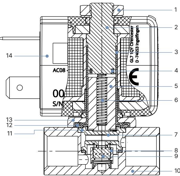
| No. | Element | Material |
|---|---|---|
| 1 | Nut | DIN 176 Surface finish thick film passivated KOSA0101 |
| 2 | Stopper | Stainless steel 1.4113/434 |
| 3 | Core guide tube | Stainless steel 1.4303 ST/305L |
| 4 | Shading ring | Copper (optional silver) |
| 5 | Core | Stainless steel 1.4113/434 |
| 6 | Spring | Stainless steel 1.4310/301 |
| 7 | Insert | PEEK GF30 |
| 8 | Seal holder | PEEK GF30 |
| 9 | Seat seal | FKM |
| 10 | Valve body | Brass, stainless steel 1.4305/303, PA (polyamide) |
| 11 | Seal | FKM/EPDM |
| 12 | O-ring | FKM/EPDM |
| 13 | Flange | Surface finish thick film passivated KOSA0101 (brass variant), Nickel-plated surface (stainless steel variant) |
| 14 | Coil | Epoxy |
Threaded variant
Note
Dimensions in mm. Variants according to industry standard form B.
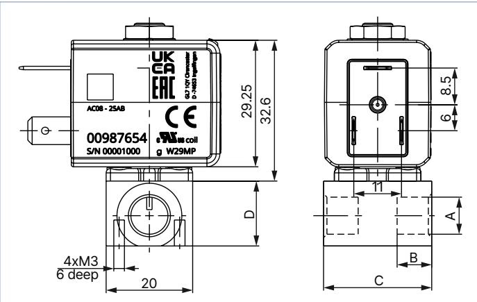
| Port connection | A [mm] | B [mm] | C [mm] | D [mm] |
|---|---|---|---|---|
| Thread CF B (G 1/8) | 8 | 34 | 14 | - |
| Thread CF B (NPT 1/8) | 7 | 34 | 14 | - |
DANGER
Risk of injury due to high pressure in the system or device Before working on the system or device, switch off the pressure and ventilate and empty the lines.
Risk of injury from electric shock Before working on the system or device, switch off the power supply and secure against reactivation. Observe the applicable accident prevention and safety regulations for electrical devices.
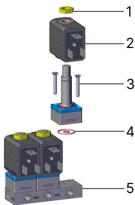
WARNING
Risk of electric shock if protective conductor not connected Always connect the protective conductor. Check electrical continuity between the solenoid and the body.
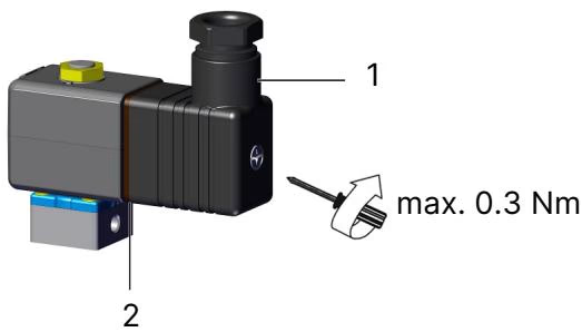
WARNING
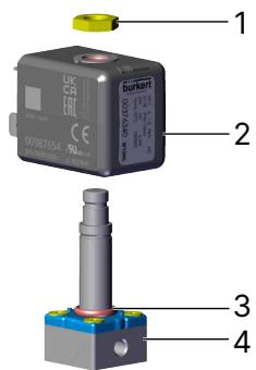
Risk of injury due to overheating or fire hazard Connecting the coil without a pre-assembled armature will cause overheating and destroy the coil. Only connect the coil after the armature has been installed.
The solenoid can be rotated by 4 × 90° or 2 × 180° in case of a block installation.
Explore similar products in our catalog