PN16

BURKERT Type 6013 (20017164) direct-acting 2/2-way plunger valve. Features a 4.0mm orifice, brass body, FKM seal, flange connection, and 12V DC operation.
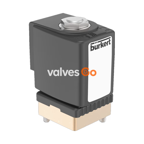
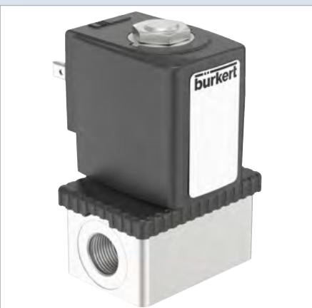
BURKERT 20017164 Type 6013 is a direct-acting and compact 2/2-way plunger valve designed for reliable fluid control up to DN 6.0. The stopper and the core guide tube are welded together to increase pressure resistance and leak-tightness. This specific model features a 4.0mm orifice, a brass body, FKM seals, and operates on 12V DC. A Bürkert-specific flange variant (SFB) enables the space-saving arrangement of valves on a multiple manifold. The valve utilizes a vibration-proof, bolted coil system for enhanced durability.
| Product Properties | Specification |
|---|---|
| Dimensions | See Dimensions section |
| Seal Material | FKM (Fluor rubber) |
| Body Material | Brass |
| Coil Material | Polyamide, epoxy |
| Orifice | DN 4.0 mm |
| Circuit Function | A (Normally closed) |
| Thermal Insulation Class | Polyamide coil class B, Epoxy coil class H |
| Duty Cycle | 100% continuous operation |
| Operating Voltage | 12 V DC |
| Voltage Tolerance | ±10% |
| Operating Medium | Technical vacuum, neutral gases and liquids (e.g., compressed air, water, hydraulic oil) |
| Medium Temperature | -10 °C to +100 °C (PA coil) |
| Viscosity | Max. 21 mm²/s |
| Electrical Connection | Plug contacts according to DIN EN 175 301 - 803 form A |
| Port Connection | Flange (Bürkert flange 32 x 32 version C1) |
| Degree of Protection | IP65 with suitable connector |
| Installation Position | As required, preferably with actuator upright |
| Ambient Temperature | Max. +55 °C |
Circuit Function A (CF A): 2/2-way solenoid valve, direct-acting, normally closed. When de-energized, the actuator moves the valve to the fail-safe position, closing the flow path through the valve body.
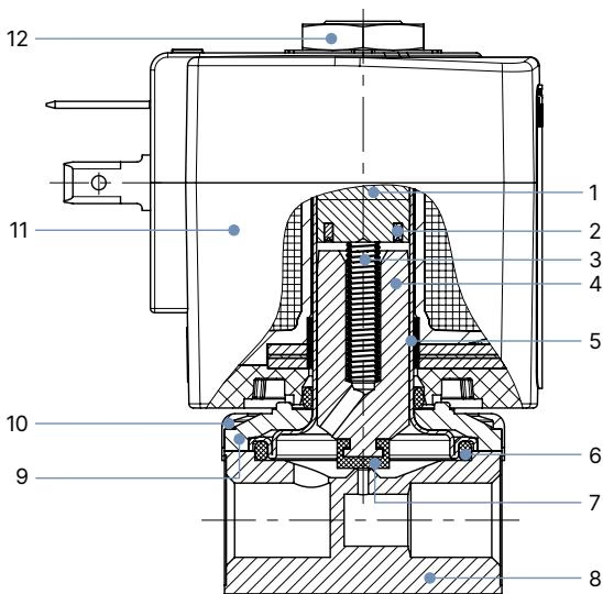
| No. | Element | Material |
|---|---|---|
| 1 | Stopper | Stainless steel 1.4105/430F |
| 2 | Shading ring | Cu (brass variant) / Ag (stainless steel variant) |
| 3 | Spring | Stainless steel 1.4310/301 |
| 4 | Magnetic core | Stainless steel 1.4105/430F |
| 5 | Core guide tube | Stainless steel 1.4303/305/308 |
| 6 | Seal | FKM |
| 7 | Armature seal | FKM |
| 8 | Valve body | Brass |
| 9 | Sub-base | Steel, surface finish thick-film passivated (brass variant) |
| 10 | Cover | Polyamide |
| 11 | Coil | PA (polyamide) / Epoxy |
| 12 | Nut | Steel, surface finish thick-film passivated (brass variant) |
INFO
Note: Dimensions are in mm.
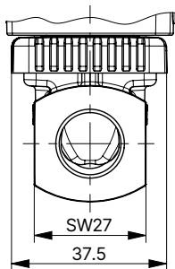
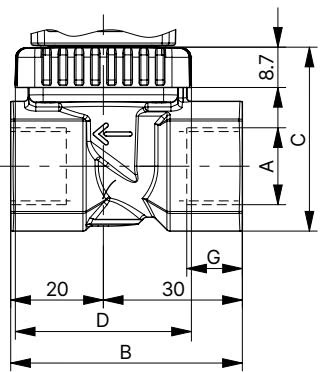
| Port Connection | A [inch] | B [mm] | C [mm] | D [mm] | G [mm] |
|---|---|---|---|---|---|
| Flange | - | 32 | 14.3 | 32.6 | - |
| Coil Size | E [mm] | F [mm] |
|---|---|---|
| 5 | 32 | 45 |
| 6 | 40 | 51 |
Power Consumption (Circuit Function A)
| Orifice [mm] | Power Consumption | Electrical Power Inrush AC [VA] | Electrical Power Hold AC [VA] | Coil Size | Opening Time [ms] | Closing Time [ms] |
|---|---|---|---|---|---|---|
| 4.0 | 8 W AC or 8 W DC (9) | 24 | 17 | 5 (32 mm) | 20 | 30 |
| 4.0 | 10 W AC or 10 W DC (11) | 30 | 22 | 6 (40 mm) | 20 | 30 |
(Values in brackets correspond to a coil temperature of +20 °C)
WARNING
High Pressure Danger! Before loosening lines and valves, turn off the pressure and vent the lines. Observe the flow direction during installation. Comply with applicable accident prevention and safety regulations for pressure equipment.
Explore similar products in our catalog