

PN16

BURKERT 20025930 (Type 8652) AirLINE is a 16-slot modular valve island featuring PROFIBUS DPV1 communication, AirLINE Quick aluminium plate, HotSwap capability, and integrated SIA safety shutdown.
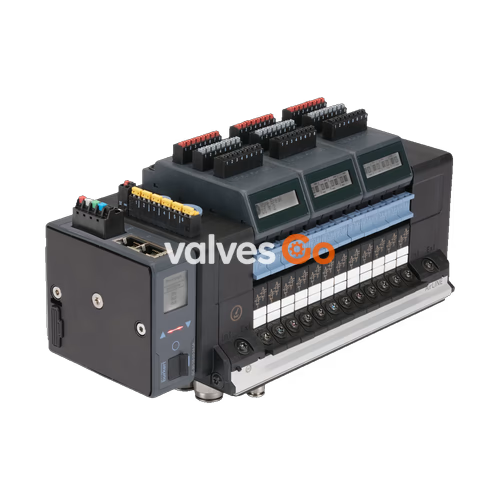
BURKERT 20025930 (Type 8652 AirLINE) is a 16-station modular valve island engineered for process automation environments. Configured as a high-density pneumatic automation node, this assembly integrates 16 valve slots accommodating 32 total valve pilot functions, 32 digital inputs across four 8DI electronic modules, and an integrated central pneumatic intermediate feed module. Fieldbus connectivity is established through a dedicated ME43 PROFIBUS DPV1 communication interface with a 9-pin Sub-D socket, providing cyclic process command exchange as well as clear-text and symbolic diagnostic alarms readable directly via an on-board LC display or transmitting to the higher-level PLC.
Process safety and system availability are central to the 20025930 configuration. The first 13 valve slots are populated with Type 6534 dual 3/2-way normally closed valves (CF-C) with manual override, while positions 14 through 16 are equipped with Type 6534 SIA variants designed for safety-related hardware shutdown via external potential-free contacts. Integrated check valves in exhaust air ducts 3 (R) and 5 (S) prevent back-pressure surges from causing unintended process valve movements. In addition, pneumatic HotSwap capability in supply channel 1 (P) permits valve replacement under full line pressure without interrupting adjacent operating loops.
| Configuration Parameter | Factory Setting / Specified Hardware |
|---|---|
| Base Type | Type 8652 AirLINE Standard |
| Article Number (MPN) | 20025930 |
| Number of Valve Slots | 16 valve slots (accommodating 32 discrete valve functions) |
| Valve Positions 1 to 13 | 2x 3/2-way CF-C (normally closed, servo-controlled, with manual override) |
| Valve Positions 14 to 16 | 2x 3/2-way CF-C SIA (normally closed, safety-related shut-off) |
| Digital Inputs | 32 DI (El. module 1, 2, 3, and 4 equipped with DI) |
| Fieldbus Communication | PROFIBUS DPV1 (ME43 architecture, Sub-D 9-pin interface) |
| AirLINE Quick Adapter Plate | Anodised aluminium (for control cabinet base or wall mounting) |
| Supply Connection 1 (P) | Push-in D10 mm (nickel-plated brass) |
| Working Ports 2 & 4 | Push-in D6 mm (nickel-plated brass) |
| Auxiliary Pilot Air | Internal supply (3 to 10 bar) |
| Pneumatic Intermediate Feed | 1 unit integrated (intermediate supply/exhaust module) |
| Exhaust Check Valves | Integrated in exhaust channels 3 (R) and 5 (S) |
| Pneumatic HotSwap | Integrated in supply port 1 (P) |
| Specification Parameter | Value / Technical Requirement |
|---|---|
| Operating Medium | Oil-free or lubricated compressed dry air, neutral gases (5 μm filtration recommended) |
| Compressed Air Quality | ISO 8573-1:2010, Class 7.4.4 |
| Operating Pressure Range | Vacuum to 10 bar (-1.0 to 10.0 bar) overpressure to atmospheric |
| Auxiliary Pilot Pressure | 3 to 10 bar |
| Standard Flow Rate $Q_{\text{Nn}}$ (Air) | 310 l/min (measured at +20 °C, 6 bar inlet pressure, 1 bar pressure drop) |
| Flow Rate with HotSwap Function | Approx. 3% flow reduction ($Q_{\text{Nn}} \approx 300\text{ l/min}$) |
| Switching Times (ISO 12238) | Opening: 15 to 20 ms; Closing: 15 to 25 ms (varies by circuit function) |
| Nominal Operating Mode | Continuous operation (100% duty cycle) |
| Station Width | 11 mm per valve slice |
| Body / Seal Materials | Polyamide (PA) housing; NBR and PUR seals |
| Operating Voltage | 24 V DC (±10%, residual ripple 1 Vss) |
| Nominal Power per Valve | 0.7 W (drops to 0.175 W after electronic power reduction) |
| Nominal Current per Valve | 29 mA (drops to 10 mA after electronic power reduction) |
| Degree of Protection | IP20 bare mounting; IP65 inside closed cabinet with AirLINE Quick |
| Ambient / Medium Temperature | -10 °C to +55 °C |
| Storage Temperature | -20 °C to +60 °C |
| Electrical Protection Class | Class III according to DIN EN 61140, VDE 0140 |
Direct cabinet integration is achieved through the AirLINE Quick adapter plate, eliminating the need for bulkheads and intermediate cabinet fittings by mounting the valve island directly onto the control cabinet floor or wall cutout.
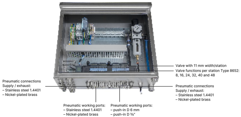
| Property | AirLINE Quick Specification |
|---|---|
| Adapter Plate Material | Anodised aluminium (optional stainless steel 1.4301 available) |
| Pneumatic Port Material | Nickel-plated brass (push-in) |
| Supply / Exhaust Ports | Push-in coupling D10 mm (or 3/8") |
| Working Outlets | Push-in coupling D6 mm (or 1/4") |
| Mounting Position | Control cabinet floor or control cabinet wall |
| Ingress Protection | IP65 achieved within enclosed control cabinets |
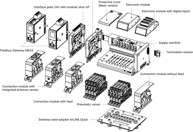
The 8652 architecture combines pneumatic base modules, electrical backplane slices, electronic I/O modules, and the main fieldbus gateway into a unified rail-mountable structure.
The Type 6534 pilot valves mounted on the island provide high-speed servo-assisted switching:
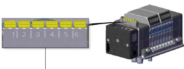
Valve positions 14, 15, and 16 on article 20025930 are fitted with Type 6534 SIA valves. These valves feature dedicated, physically separate connection terminals allowing external hardware interlocks to cut valve coil power independently of the bus master communications.
| Feature | SIA Technical Specification |
|---|---|
| Valve SIA Terminal Type | Pluggable, coded 2-pin screw terminals ($0.14\text{ to }1.5\text{ mm}^2$, AWG 28–16) |
| Module Shutdown Terminal | Pluggable spring-loaded terminal strip, 12-pin ($0.14\text{ to }1.5\text{ mm}^2$, AWG 26–16) |
| Switching Capacity | 0.5 A / 24 V DC (individual valve); 1.5 A / 24 V DC (module shutdown) |
| Factory Delivery State | Bridged with factory jumper clips for direct commissioning without SIA |
| Control Contact Requirement | External potential-free dry contact (safety relay or mechanical switch) |
Safety Terminal Preparation
Before wiring an external safety shut-off contact to the SIA terminals, the yellow coded jumper clips pre-installed at delivery must be removed. Connecting voltage to these potential-free inputs will damage the shutdown circuitry.
| Terminal | Wire Color | Assignment |
|---|---|---|
| 1 | Red | +24 V DC (electronics power) |
| 2 | White | CAN_H (internal büS connection) |
| 3 | Green | Shielding (PE) |
| 4 | Blue | CAN_L (internal büS connection) |
| 5 | Black | 0 V DC (GND) |
| Pin | Wire Color | Assignment |
|---|---|---|
| 1 | Red | AUX +24 V DC (pneumatic coil load power) |
| 2 | Black | 0 V DC (GND) |
Isolated Power Supplies
The pneumatic valves must be supplied via their own dedicated 2-pin AUX 24 V power connection on the interface plate. This keeps solenoid coil load noise isolated from the sensitive display and PROFIBUS digital communications.
| Sub-D Pin | Signal Name | Description |
|---|---|---|
| 1 | SHIELDING | Cable shielding connection |
| 2 | M24 | Optional 24 V ground return |
| 3 | RxD / TxD-P | B-line (receive/transmit data positive) |
| 4 | CNTR-P | Control signal P (repeater direction control, optional) |
| 5 | DGND | Data ground (0 V reference for terminating resistors) |
| 6 | +5 V | +5 V DC power for active bus terminating resistors |
| 7 | +24 V | Optional +24 V DC feed |
| 8 | RxD / TxD-N | A-line (receive/transmit data negative) |
| 9 | CNTR-N | Control signal N (optional) |
Article 20025930 includes four 8DI electronic modules, providing 32 total digital sensor inputs across the 16 valve stations (2 inputs per valve position). Current consumption is limited to 30 mA per digital input channel.
| Parameter | Digital Input Module Specification |
|---|---|
| Supported Sensors | Standard 3-wire PNP sensors, 2-wire sensors (10 to 30 V), mechanical limit switches |
| Switching Thresholds | $V_{\text{OFF}} = 0\text{ to }5\text{ V DC}$; $V_{\text{ON}} = 10\text{ to }30\text{ V DC}$ |
| Input Current at $V_{\text{ON}}$ | Maximum 5.7 mA per channel (typical at 24 V DC) |
| Input Impedance | $>4\text{ k}\Omega$ |
| Galvanic Isolation | None (all channels share a common 0 V reference potential) |
| Conductor Cross-Section | Pluggable screw terminals, $\le 1.5\text{ mm}^2$ (AWG 28–16) |
| Maximum Cable Length | $<30\text{ m}$ |
| Sensor Diagnostics | Wire-break detection on 2-wire sensors; short-circuit detection on 3-wire sensors |
Dimensions are stated in millimetres (mm) for the 16-fold variant with integrated central intermediate air supply module.
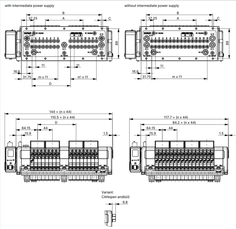
| Dimension Variable | 16-Fold with Intermediate Feed | 16-Fold without Intermediate Feed |
|---|---|---|
| Dimension A | 112 mm | 99 mm |
| Dimension B | 224 mm | 198 mm |
| Mounting Pattern C | 10 × M5 | 10 × M5 |
| Dimension D | 114.3 mm | — |
| Increment m | 7 | 15 |
| Increment $m'$ | 7 | — |
| Segment Number n | 4 | 4 |
When positioning the valve island on the control cabinet baseplate or cutout, observe minimum front clearance distances to permit valve module removal under operating conditions.
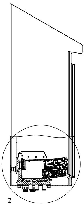
Maintenance Without Process Interruption
Pneumatic HotSwap enables replacement of an individual pilot valve while the manifold remains pressurized. Maintain at least the recommended front enclosure distance shown in the manual so technicians can unlock and dismount the valve body cleanly.
Type 8652 assemblies carrying explosion-proof codes PU17 or PX68 comply with European ATEX, international IECEx, North American HazLoc, and Chinese CCC Ex directives for Category 3 equipment.
| Standard / Certification | Protection Classification |
|---|---|
| ATEX Certificate (DEKRA BVS) | BVS 20 ATEX E 031 U; II 3G Ex ec IIC Gc / II 3D Ex tc IIIC Dc |
| IECEx Certificate | IECEx BVS 20.0024 U; Ex ec IIC Gc / Ex tc IIIC Dc |
| North America (cURus HazLoc) | Class I, Zone 2, AEx ec IIC Gc / Ex ec IIC Gc U; Class II, Zone 22, AEx tc IIIC Dc; Class I Div 2 Groups A, B, C, D; Class II/III Div 2 Groups F, G |
| China Compulsory Certification | CCC Ex certification according to GB/T 3836 series |
| Enclosure Requirement | Minimum IP54 for gas (Zone 2 / 3G); minimum IP6X for dust (Zone 22 / 3D) |
| Environmental Limitation | Pollution degree 2 or better per IEC 60664-1; indoor cabinet use only |
| Transient Protection | External transient protection must clamp surges to $\le 140%$ of nominal peak voltage |
Explosion Hazard in Hazardous Locations
Do not connect or disconnect electrical terminals, fieldbus plugs, or SIA wiring while circuits are energized in an explosive atmosphere. The pneumatic HotSwap function must never be used in a potentially explosive atmosphere unless the environment is proven non-hazardous by calibrated gas detection equipment.
| Article Description | Ordering Code (Article No.) |
|---|---|
| 20025930 Configured Valve Island (16-bank, PROFIBUS DPV1, ALQ AL) | 20025930 |
| Type 6534 Replacement Valve, 2x 3/2-way CF-C (standard with override) | 301374 |
| Type 6534 SIA Replacement Valve, 2x 3/2-way CF-C SIA (safety shutdown) | 338802 |
| 8DI Electronic Module (with 8 digital input contacts) | 384872 |
| 5-Pin Spring-Loaded Terminal Strip (display & electronics power) | 920180 |
| 2-Pin Spring-Loaded Terminal Strip (auxiliary valve power AUX 24 V) | 920442 |
| ME43 Fieldbus Gateway Replacement — PROFIBUS DP | 301803 |
| ME43 Fieldbus Gateway Replacement — Industrial Ethernet | 301799 |
| M5 × 10 A2 DIN 6912 Base Screw Set (pack of 10 for cabinet mounting) | 308661 |
| Height Adapter Plate (16-fold with intermediate feed) | 754962 |
| Retaining Plate for External Cabinet Mounting (16-fold with feed) | 60005568 |
| Blind Plate (16-fold with intermediate feed) | 754967 |
Explore similar products in our catalog


