Up to 99.8% Efficiency

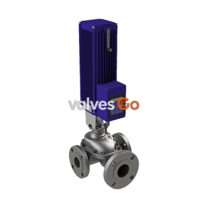
Burkert Type 3281 electromotive 2-way globe proportional valve with integrated positioner or process controller. Features stepper motor, DN15, up to 130°C.
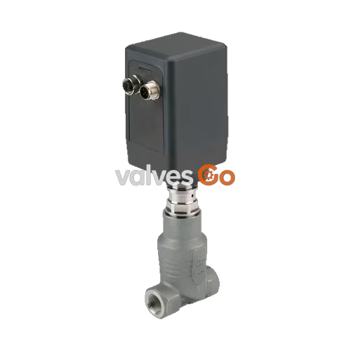
The Burkert Type 3281 direct-acting electromotive 2-way proportional valve is particularly suitable for dosing liquids and gases in closed or open control loops. The valve is driven by a linear stepper motor. The integrated electronics assembly simplifies process integration, meaning additional actuation modules are not necessary. The motor does not need any energy to maintain a certain valve opening. This feature can reduce the energy consumption of a plant dramatically and therefore make it more efficient.
The Type 3281 is available as a variant with an integrated positioner, as well as a variant with an integrated process controller. The valve spindle is rigidly connected to the threaded spindle and driven by the stepper motor, converting rotary movement into linear movement to regulate flow.
Key Features:
| Product Properties | Specification |
|---|---|
| Seal | PTFE |
| Valve body | Stainless steel |
| Flow direction | Against closing direction (below seat) |
| Design | Globe: on/off valve or control valve Angle seat: on/off valve or control valve |
| Weight | ~1.1 kg |
| Orifice | DN 15, NPS 1/2 |
| Controller variant | On/off valve or position controller or process controller |
| Dead band of position control | ±0.5% (corresponds to setting range 1:100) |
| Closing time | 2.5 s |
| Operating pressure | 0...16 bar(g) (depending on seat size) Vacuum variant up to -0.9 bar(g) (optional) |
| Duty cycle | Up to 100% (depending on medium and ambient temperature) |
| Kvs value | 0.57...4.55 m³/h |
| Nominal pressure | PN 25 (DIN EN 1333) |
| Seat leakage | Class VI (DIN EN 60534-4) |
| Operating voltage | 24 V DC ± 10% (max. residual ripple 10%) |
| Power consumption | <1 W holding power Max. 12 W (short term 20 W) |
| Operating medium | Neutral gases and liquids |
| Medium temperature | -20 °C...+130 °C |
| Viscosity | Max. 600 mm²/s (cSt) |
| Degree of protection | IP54 |
Energy Efficiency
The stepper motor is only supplied with energy when it opens or closes the valve further. Owing to the internal holding torque, the stepper motor only moves when it is controlled. In the remaining time, only the control electronics need a basic voltage supply.
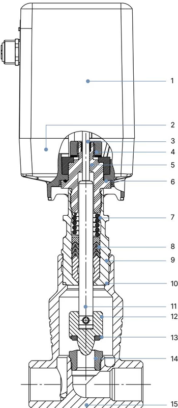
| No. | Element | Material |
|---|---|---|
| 1 | Housing cover | PC (Polycarbonate) |
| 2 | Housing base | PPS (Polyphenylenesulfide) |
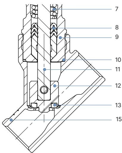
| No. | Element | Material |
|---|---|---|
| 3 | Spindle guide | High-performance polymer |
| 4 | Sliding washers | High-performance polymer |
| 5 | Guide piece | Stainless steel 1.4305 |
| 6 | O-ring | NBR |
| 7 | Compression spring | Stainless steel |
| 8 | Spindle seal | PTFE (filled)/FKM, with spring compensation |
| 9 | Pipe | Stainless steel 1.4404 |
| 10 | Body seal | Graphite |
| 11 | Spindle | Stainless steel 1.4401 |
| 12 | Control cone/swivel plate | Stainless steel 1.4571 |
| 13 | Seat seal | PTFE sealing washer |
| 14 | Valve seat | Stainless steel 1.4571 |
| 15 | Valve body | Stainless steel CF3M/316L |
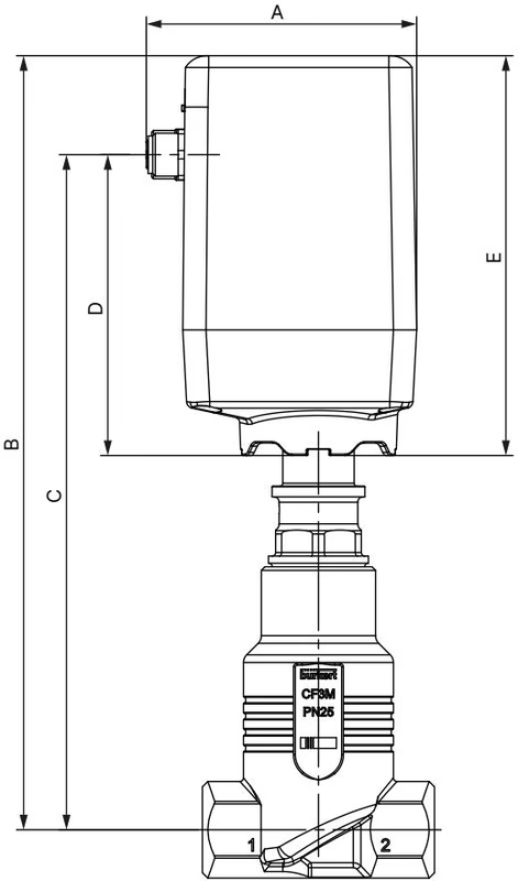
| A | B | C | D | E | F | G | H | I | J |
|---|---|---|---|---|---|---|---|---|---|
| 76 | 216 | 188 | 84 | 112 | 52 | 66 | 45 | 58 | 20 |
(Dimensions in mm. Twisting of the actuator housing is possible.)
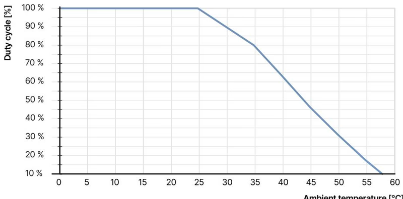
The duty cycle is an important factor for motor valves. The self-heating of the engine limits the maximum duty cycle. High ambient temperatures additionally increase the risk of damage due to overheating. The following diagram shows the recommended maximum duty cycle as a function of the ambient temperature.
Duty Cycle Limits
Operating the valve outside the recommended duty cycle limits will result in a significantly reduced service life of the valve. The duty cycle refers to the motor, which is only switched on when the valve is to move.
| Valve function | Seat size | Controller variant | Port connection | Kvs value [m³/h] | Pressure range [bar(g)] |
|---|---|---|---|---|---|
| Globe (Control) | 4 | Control | G 1/2 | 0.57 | 0...16 |
| Globe (Control) | 6 | Control | G 1/2 | 1.25 | 0...16 |
| Globe (Control) | 8 | Control | G 1/2 | 1.8 | 0...12 |
| Globe (Control) | 10 | Control | G 1/2 | 2.25 | 0...7 |
| Globe (On/off) | 15 | On/off | G 1/2 | 4.45 | 0...3.5 |
| Angle-seat (Control) | 15 | Control | G 1/2 | 3.6 | 0...3 |
| Angle-seat (On/off) | 15 | On/off | G 1/2 | 4.55 | 0...3.5 |
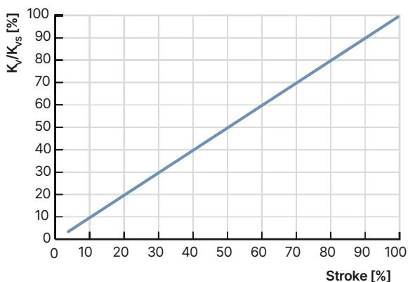
The dimensioning of the seat size is very important for electromotive proportional valves to function properly within the application. The seat size must be selected so that the desired flow range is achieved and, when the valve is fully open, a sufficient portion of the total pressure drop occurs across the valve (Reference value: Δp valve > 25% of the total pressure drop).
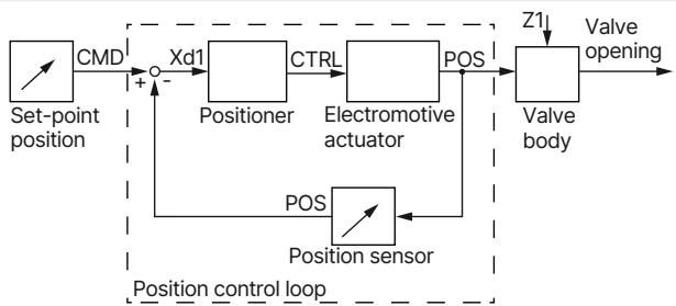
The proportional valve in the position control variant converts an external standard signal, the position set-point value, into a valve position. The position of the actuator is controlled according to the set-point position. The position sensor records the current position (POS) of the electromotive valve. This actual position is compared by the positioner with the set-point value (CMD) specified as the standard signal. If there is a control difference, a motor control signal is given to the actuator as the actuating variable.
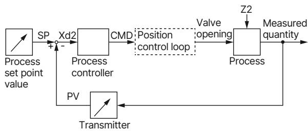
The additionally implemented PID controller can perform not only the actual position control but also a process control in the sense of a cascade control. The process controller is integrated into a control loop. The position setpoint of the valve is calculated from the process setpoint and the actual process value via the control parameters (PID controller).
Explore similar products in our catalog