

PN16

BURKERT 20032925 Type 8652 is a 20-slot AirLINE valve island with stainless steel AirLINE Quick plate, Industrial Ethernet, 40 digital inputs, 18 pre-installed valves, and -1 to 10 bar operating pressure.
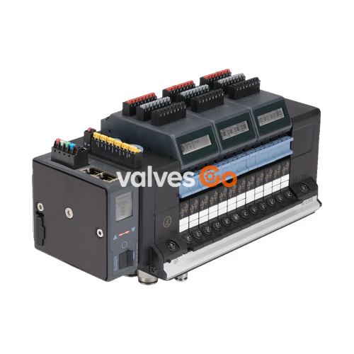
BURKERT 20032925 (Type 8652) is a 20-slot modular AirLINE valve island engineered for process automation, featuring a factory-integrated stainless steel 1.4301 AirLINE Quick adapter plate and an Industrial Ethernet gateway supporting PROFINET IO, EtherNet/IP, Modbus TCP, EtherCAT, and CC-Link IE Field Basic. The unit features 40 discrete digital inputs across five 8DI modules, internal auxiliary pilot air, stainless steel 1.4401 push-in fittings (D 3/8" supply and D 1/4" working ports), and an intermediate pneumatic feed module.
Diagnostic functions are displayed directly on the LC display in both clear text and standardized symbols, reducing commissioning and maintenance times while transmitting real-time plant diagnostics to the supervisory PLC. Process reliability is enhanced through integrated pneumatic check valves located in the exhaust channels, preventing pressure spikes from generating unplanned actuator movements.

Article 20032925 is fully pre-assembled with a dedicated valve and slot configuration as detailed below:
| Slot Position | Configured Element | Circuit Function Details |
|---|---|---|
| Position 1 to 14 | 5/2-way bistable valve (CF-Z) | Servo-controlled impulse valve with 2 coils and manual override |
| Position 15 to 17 | 2x 3/2-way valve (CF-C) | Servo-controlled, normally closed with manual override |
| Position 18 | 5/2-way monostable valve (CF-H) | Servo-controlled with manual override |
| Position 19 to 20 | Blind plate | Sealing plate for unpopulated valve slots |
| Parameter | Specification |
|---|---|
| Body Material | PA (Polyamide) |
| Seal Materials | NBR and PUR |
| Station Width | 11 mm per valve slice |
| Operating Pressure Range | -1.00 bar to 10.00 bar (vacuum to 10 bar) |
| Pilot Pressure Range | 3.00 bar to 10.00 bar (internal auxiliary pilot air) |
| Flow Rate $Q_{Nn}$ (Air) | 310 l/min (at +20 °C, 6 bar inlet pressure, 1 bar pressure drop) |
| Duty Cycle | Continuous operation (100% ED) |
| Switching Time Measurement | Measured according to ISO 12238 |
| Operating Voltage | 24 V DC (±10%), residual ripple 1 $V_{ss}$ |
| Power Consumption per Valve | 0.7 W nominal (0.175 W after internal power reduction) |
| Current Consumption per Valve | 29 mA nominal (10 mA after internal power reduction) |
| Electrical Protection Class | Class III according to DIN EN 61140, VDE 0140 |
| Operating Medium | Lubricated or non-lubricated compressed air, neutral gases (5 µm filter recommended) |
| Compressed Air Quality | ISO 8573-1:2010, Class 7.4.4 |
| Ambient & Medium Temperature | -10 °C to +55 °C |
| Storage Temperature | -20 °C to +60 °C |
| Ingress Protection | IP20 standalone; IP65 inside closed cabinet with AirLINE Quick plate |
| Cabinet Enclosure Rating | Type 4X per NEMA 250 (stainless steel variant in closed cabinet) |
| Standards & Approvals | cULus Listed (UL 61010-1, CAN/CSA-C22.2 No. 61010-1) |
The integrated AirLINE Quick adapter plate allows direct mounting of the valve terminal into the bottom floor or side wall of a control cabinet, cutting down cabinet volume requirements and eliminating internal bulkhead tubing connections.
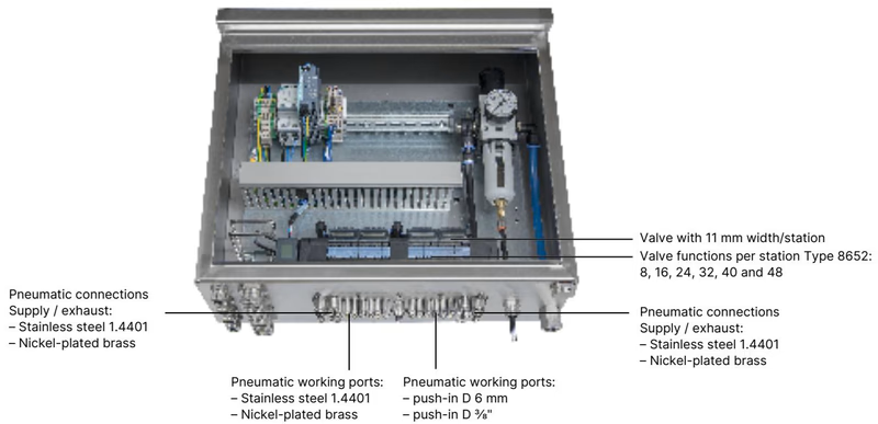
Article 20032925 utilizes the 20-valve slot base with an integrated intermediate pneumatic supply module.
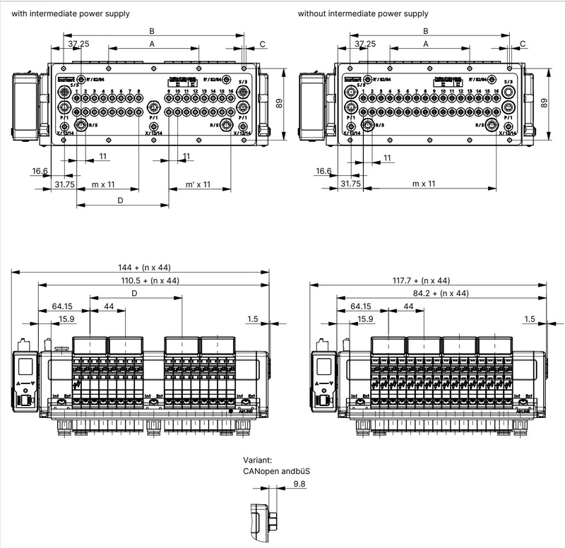
| Variant | A (mm) | B (mm) | C | D (mm) | m | m' | n |
|---|---|---|---|---|---|---|---|
| 20-fold with intermediate supply | 134 | 268 | 10 × M5 | 158.3 | 11 | 7 | 5 |
Cabinet Clearance Requirements
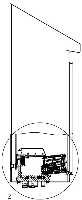
To maintain access to pneumatic components, cable connectors, and display modules, adhere to the minimum mounting distances between the mounting plate and the cabinet door/front edge, as well as the cabinet rear wall.
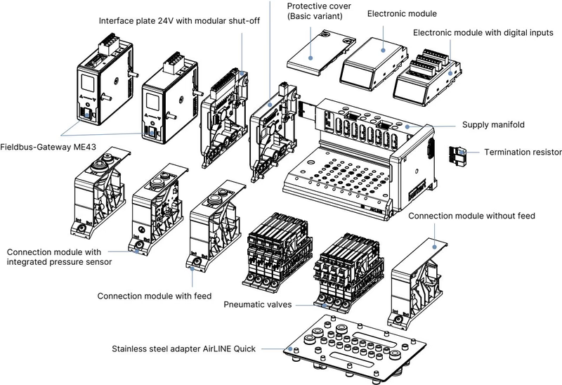
The valve terminal utilizes dedicated physical terminals for logic and valve power:
Independent Power Supplies
The pneumatic valves and the main communication electronic module must be supplied via electrically separated circuits to prevent coil switching transients from disrupting fieldbus data communication.
The ME43 Industrial Ethernet communication gateway provides two M12/RJ45 Ethernet ports (X1 and X2) supporting PROFINET IO, EtherNet/IP, Modbus TCP, EtherCAT, and CC-Link IE Field Basic.
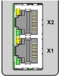
| RJ45 Pin | Signal Assignment |
|---|---|
| 1 | TX+ (Transmit Data +) |
| 2 | TX- (Transmit Data -) |
| 3 | RX+ (Receive Data +) |
| 4 | Not connected (N.C.) |
| 5 | Not connected (N.C.) |
| 6 | RX- (Receive Data -) |
| 7 | Not connected (N.C.) |
| 8 | Not connected (N.C.) |
Article 20032925 includes five digital input modules providing a total of 40 digital inputs for limit switch feedback from connected process valves.
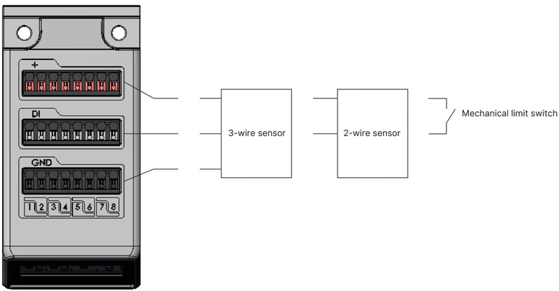
| Parameter | Value |
|---|---|
| Supported Sensors | Standard 3-wire sensors, 2-wire sensors (10–30 V), mechanical limit switches |
| Supply Voltage per DI | 24 V DC (from electronic module, max 30 mA per input) |
| Conductor Cross-Section | ≤ 1.5 mm² |
| Maximum Cable Length | < 30 m |
| Input Voltage Thresholds | $V_{OFF} = 0\dots5\text{ V}$, $V_{ON} = 10\dots30\text{ V}$ |
| Input Current at $V_{ON}$ | Max. 5.7 mA per channel (typical at 24 V DC) |
| Input Impedance | > 4 kΩ |
| Galvanic Isolation | None (common reference potential across all channels) |
| Diagnostics | 3-Wire Sensor | 2-Wire Sensor | Mechanical Limit Switch |
|---|---|---|---|
| Sensor Actuated | Yes | Yes | Yes |
| Sensor Not Actuated | Yes | Yes | Yes |
| Short Circuit Detection | Yes | — | — |
| Wire Break Detection | — | Yes | — |
The pilot valves mounted on the Type 8652 terminal belong to the Type 6534 family (actuated by Type 6164 pilot solenoids). Replacement valves and spare components can be identified via the following ordering data:
| Circuit Function | Width | Nominal Orifice | $Q_{Nn}$ (Air) | Pressure Range | Response Time Open / Close | Article No. (incl. screws) |
|---|---|---|---|---|---|---|
| CF-C (3/2-way NC) | 11 mm | 4 mm | 270 l/min | Vac. to 10 bar | 15 ms / 15 ms | 20102334 (Ref. 20088974) |
| 2x CF-C (2x 3/2-way NC) | 11 mm | 4 mm | 270 l/min | Vac. to 10 bar | 15 ms / 15 ms | 301374 (Ref. 296031) |
| 2x CF-D (2x 3/2-way NO) | 11 mm | 4 mm | 310 l/min | Vac. to 10 bar | 15 ms / 15 ms | 301375 (Ref. 296032) |
| CF-H (5/2-way monostable) | 11 mm | 4 mm | 290 l/min | Vac. to 10 bar | 20 ms / 25 ms | 301376 (Ref. 296033) |
| CF-Z (5/2-way bistable impulse) | 11 mm | 4 mm | 290 l/min | Vac. to 10 bar | 20 ms / 25 ms | 301377 (Ref. 296034) |
| CF-L (5/3-way closed center) | 11 mm | 4 mm | 275 l/min | Vac. to 10 bar | 15 ms / 15 ms | 301380 (Ref. 296036) |
| CF-M (5/3-way ventilated) | 11 mm | 4 mm | 300 l/min | Vac. to 10 bar | 20 ms / 20 ms | 301379 (Ref. 296035) |
| CF-N (5/3-way exhausted) | 11 mm | 4 mm | 300 l/min | Vac. to 10 bar | 20 ms / 20 ms | 301381 (Ref. 296039) |
| Blind plate | 11 mm | — | — | — | — | 335779 (Ref. 327614) |
AirLINE Type 8652 equipped with Industrial Ethernet operates as a master communication gateway on the plant fieldbus while interconnecting distributed sub-stations or büS slave terminals.
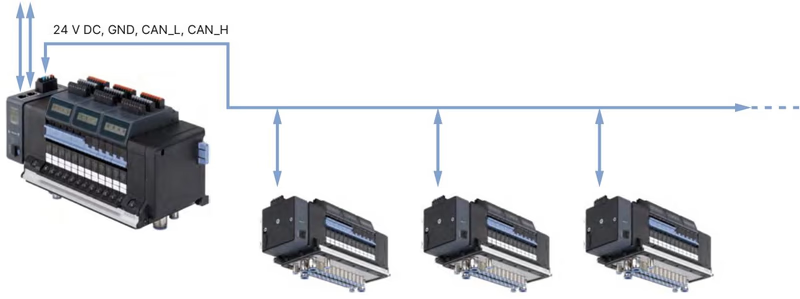
The Bürkert Communicator software operates on the EDIP (Efficient Device Integration Platform) architecture:
Gateway Configuration
The integrated ME43 fieldbus gateway module must have its device description file generated and configured via the Bürkert Communicator tool before system commissioning.
Article 20032925 is certified under cULus Listed files according to UL 61010-1 and CAN/CSA-C22.2 No. 61010-1, providing Type 4X environmental protection per NEMA 250 when mounted in an appropriate enclosure.
For installations in hazardous atmospheres (ATEX/IECEx Zone 2/22, Class I Div 2 under supplementary approvals PX68 / PU17), the following operating conditions apply:
Explore similar products in our catalog


