

PN16

BURKERT 20033486 Type 8652 AirLINE 12-slot valve island features 10 bistable 5/2-way valves, 2 blind plates, 24 digital inputs, stainless steel AirLINE Quick plate, HotSwap, and Industrial Ethernet.
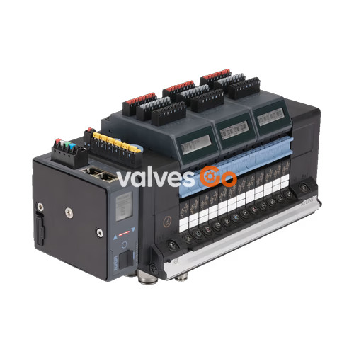
BURKERT 20033486 (Type 8652) is a 12-slot AirLINE valve island configured for process automation applications, combining high pneumatic density with multi-protocol Industrial Ethernet communications. This pre-assembled unit is fitted with ten bistable 5/2-way impulse solenoid valves (circuit function Z) across valve slots 1 through 10, accompanied by two blind plates at positions 11 and 12 for future expansion. The valve island incorporates three 8-channel digital input modules (24 DI total) to collect discrete sensor signals directly at the pneumatic manifold.
Designed specifically for installation on control cabinet floors or rear panels, the assembly integrates a stainless steel 1.4301 AirLINE Quick adapter plate with stainless steel pneumatic fittings. The process connections comprise D10 mm push-in air supply lines and D6 mm push-in working ports. Pneumatic safety mechanisms include integrated check valves in exhaust ports 3 (R) and 5 (S) to suppress pressure peaks, as well as a pneumatic HotSwap function at port 1 (P) that allows valve replacement during continuous system operation.

The 12-station manifold operates with an internal auxiliary pilot air supply across an operating pressure range of -1.0 bar to 10.0 bar (vacuum up to 10 bar) and a pilot pressure requirement of 3.0 bar to 10.0 bar. Each 11 mm wide valve station is serviced by a low-power pilot valve (Type 6164) actuating the Type 6534 pneumatic spool valve.
Positions 1 to 10 utilize circuit function Z (CF Z), which provides a 5/2-way bistable impulse function with two coils and integrated manual overrides. Pressure applied at port 1 directs output pressure alternately to port 2 or port 4. Once pulsed, the valve retains its switched position until the opposing coil is energized. Positions 11 and 12 are blanked off using dedicated dummy plates (article 335779).
| Valve Position | Function Type | Circuit Function Symbol / Designation | Manual Override | Nominal Width |
|---|---|---|---|---|
| Position 1 to 10 | 5/2-way bistable impulse valve | Circuit function Z (CF Z), dual coil | Latching / spring return | 4 mm |
| Position 11 | Blind plate | Dummy plate module | — | — |
| Position 12 | Blind plate | Dummy plate module | — | — |
Standard Type 8652 valve stations deliver a nominal flow rate $Q_{\text{Nn}}$ of 310 l/min (measured with air at +20 °C, 6 bar inlet pressure, and 1 bar differential pressure). When utilizing the integrated pneumatic HotSwap function in supply port 1, the nominal flow rate is reduced by approximately 3% to 290–300 l/min.
Pilot Air Quality
Operate the valve island with dry, oil-free or lubricated compressed air complying with ISO 8573-1:2010 Class 7.4.4. Upstream filtration to 5 µm is recommended to ensure long operating life.
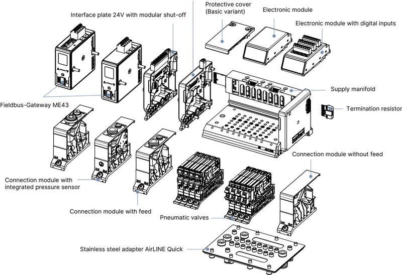
The unit is equipped with the AirLINE Quick adapter system constructed from stainless steel 1.4301, complemented by working push-in couplings made of stainless steel 1.4401. This configuration allows direct mechanical mounting into a cutout on the bottom or wall of the control cabinet. Pneumatic supply and working lines connect on the outside of the enclosure, eliminating cabinet bulkhead fittings, reducing internal tubing clutter, and minimizing overall cabinet volume.
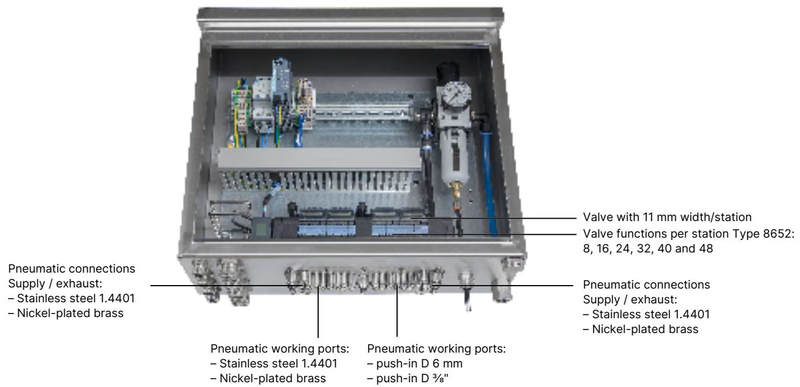
| Feature | Specification |
|---|---|
| Adapter Plate Material | Stainless steel 1.4301 |
| Pneumatic Fitting Material | Stainless steel 1.4401 |
| Supply / Exhaust Ports | Push-in connector D10 mm (3/8") |
| Working Ports (2 and 4) | Push-in connector D6 mm (1/4") |
| Auxiliary Supply (Left) | Additional D6 mm and D10 mm push-in connectors |
| Enclosure Rating | IP65 when mounted in a closed control cabinet; NEMA 250 Type 4X |
BURKERT 20033486 incorporates three 8-channel digital input (8DI) electronic modules, providing 24 independent inputs for reading feedback signals from pneumatic actuators, process valves, or position sensors. Sensors are powered with 24 V DC directly from the electronic module, with current consumption limited to a maximum of 30 mA per digital input.
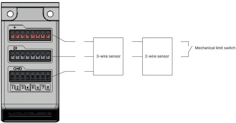
| Parameter | Specification Value |
|---|---|
| Compatible Sensors | 2-wire sensors (10–30 V), 3-wire sensors, mechanical limit switches |
| Switching Thresholds | $V_{\text{OFF}} = 0\dots5\text{ V DC}$, $V_{\text{ON}} = 10\dots30\text{ V DC}$ |
| Input Current at $V_{\text{ON}}$ | Max. 5.7 mA per channel (typical at 24 V DC) |
| Input Impedance | > 4 kΩ |
| Diagnostic Functions | Open-circuit detection (2-wire sensors), short-circuit detection (3-wire sensors) |
| Galvanic Isolation | No; all input channels share a common reference potential |
| Maximum Cable Length | < 30 m (conductor cross-section $\le 1.5\text{ mm}^2$) |
Depending on the connected sensor technology, the digital input module reports diagnostic status directly on the integrated LC display and over the fieldbus:
| Reported Sensor State | 3-Wire Sensor | 2-Wire Sensor | Mechanical Limit Switch |
|---|---|---|---|
| Sensor Actuated | Yes | Yes | Yes |
| Sensor Not Actuated | Yes | Yes | Yes |
| Short-Circuit Fault | Yes | — | — |
| Wire-Break Fault | — | Yes | — |
Communications are managed through an integrated Type ME43 fieldbus gateway module supporting Industrial Ethernet protocols: PROFINET IO, EtherNet/IP, Modbus TCP, EtherCAT, and CC-Link IE Field Basic, along with PROFINET S2 system redundancy for high-availability architectures. The physical interface consists of two shielded RJ45 ports (X1 and X2) enabling line or ring network topologies without requiring external industrial switches.
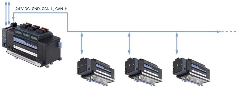
The illuminated LC display provides status indication, valve cycle counts, and diagnostic messages formatted in clear text and graphic symbols. Diagnostic messages are simultaneously transferred to the higher-level PLC. For engineering and configuration, the unit interfaces with the Bürkert Communicator software (Type 8920) via büS.
| Pin | RJ45 Signal Assignment (X1 / X2) |
|---|---|
| 1 | TX+ (Transmit Data +) |
| 2 | TX- (Transmit Data -) |
| 3 | RX+ (Receive Data +) |
| 4 | N.C. (Not connected) |
| 5 | N.C. (Not connected) |
| 6 | RX- (Receive Data -) |
| 7 | N.C. (Not connected) |
| 8 | N.C. (Not connected) |
The island utilizes electrically segregated power feeds for the digital electronics and the pneumatic solenoid coils. Separate power routing protects communication networks from inductive switching transients and permits independent safety disconnection of valve coils.
| Terminal | Wire Color | Assignment |
|---|---|---|
| 1 | Red | +24 V DC electronics power |
| 2 | White | CAN_H (büS connection) |
| 3 | Green | Shielding |
| 4 | Blue | CAN_L (büS connection) |
| 5 | Black | GND (0 V DC) |
| Terminal | Clip Number | Wire Color | Assignment |
|---|---|---|---|
| AUX 24 V | 1 | Red | +24 V DC auxiliary valve power |
| GND | 2 | Black | GND (0 V DC valve ground) |
Electrical Limits
Conductor cross-sections up to 1.5 mm² are supported by both spring-loaded terminal blocks. Transient overvoltage suppression must be configured so that peak surges do not exceed 140% of the 24 V DC nominal supply voltage.
BURKERT 20033486 has a 12-slot width profile. Mechanical installation can be completed directly through cabinet base cutouts using AirLINE Quick or mounted onto standard DIN rails (EN 50022 35 × 7.5 mm or 35 × 15 mm).
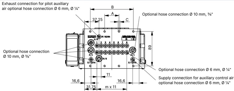
| Variant | Dimension A [mm] | Dimension B [mm] | Fixing Screws C | Pitch m | Pitch n |
|---|---|---|---|---|---|
| 4-fold | 66 | — | 4 × M5 | 3 | 1 |
| 8-fold | 35 | 111 | 8 × M5 | 7 | 2 |
| 12-fold (20033486) | 77 | 154 | 10 × M5 | 11 | 3 |
For reference across the Type 8652 family, larger manifold profiles include intermediate feed modules as detailed below:
| Variant | A [mm] | B [mm] | Screws C | D [mm] | m | $m'$ | n |
|---|---|---|---|---|---|---|---|
| 16-fold with intermediate feed | 112 | 224 | 10 × M5 | 114.3 | 7 | 7 | 4 |
| 20-fold with intermediate feed | 134 | 268 | 10 × M5 | 158.3 | 11 | 7 | 5 |
| 24-fold with intermediate feed | 156 | 312 | 10 × M5 | 158.3 | 11 | 11 | 6 |
| 16-fold without intermediate feed | 99 | 198 | 10 × M5 | — | 15 | — | 4 |
| 20-fold without intermediate feed | 121 | 242 | 10 × M5 | — | 19 | — | 5 |
| 24-fold without intermediate feed | 143 | 286 | 10 × M5 | — | 23 | — | 6 |
When positioning the valve terminal inside an enclosure, maintain minimum clearances between the terminal front edge and the cabinet door to permit hot swapping of solenoid valves.
| Category | Parameter | Specification Value |
|---|---|---|
| Materials | Housing Body | Polyamide (PA) |
| Seals | NBR and PUR | |
| AirLINE Quick Base | Stainless steel 1.4301 | |
| Push-in Connections | Stainless steel 1.4401 (working) / Stainless steel (supply) | |
| Pneumatic Data | Operating Medium | Compressed air, neutral gases (ISO 8573-1:2010 Class 7.4.4) |
| Operating Pressure | -1.0 bar to 10.0 bar (vacuum up to 10 bar) | |
| Auxiliary Pilot Pressure | 3.0 bar to 10.0 bar (internal feed) | |
| Nominal Flow Rate $Q_{\text{Nn}}$ | 310 l/min (standard); reduced by ~3% with HotSwap | |
| Width per Station | 11 mm | |
| Total Valve Slots | 12 (expandable up to 24 slots / 48 functions in family) | |
| Electrical Data | Operating Voltage | 24 V DC (±10%), residual ripple 1 Vss |
| Coil Power Consumption | 0.7 W nominal (0.175 W after electronic power reduction) | |
| Coil Current Draw | 29 mA nominal (10 mA after power reduction) | |
| Duty Cycle | Continuous operation (100% ED) | |
| Protection Class | Class III per DIN EN 61140 / VDE 0140 | |
| Environmental | Degree of Protection | IP20 standalone; IP65 in closed cabinet with AirLINE Quick |
| Ambient Operating Temp. | -10 °C to +55 °C | |
| Storage Temperature | -20 °C to +60 °C | |
| Mounting Orientation | Unrestricted (any orientation) |
Type 8652 supports safety-related shut-off architectures through optional SIA (safety shut-off) variants and module-based safety shutdown modules. In these configurations, external dry contacts directly interrupt the 24 V DC coil power circuit without requiring fieldbus interaction.
Hazardous Area Special Conditions
When installed in Zone 2 / Zone 22 hazardous locations (ATEX II 3G Ex ec IIC Gc, II 3D Ex tc IIIC Dc, IECEx BVS 20.0024 U, cURus Class I Div 2), the valve island must be installed in an enclosure rated at least IP54 for gas atmospheres or IP6X for dust atmospheres. Do not disconnect electrical terminals or perform HotSwap valve replacements while energized unless the atmosphere is verified to be non-hazardous.
| Article No. | Component Description |
|---|---|
| 20033486 | Type 8652 valve island, 12-bank, 10x CF-Z, 2x blind, 24 DI, D10/D6 VA, Industrial Ethernet |
| 301377 | Type 6534 replacement valve, CF Z (5/2-way bistable impulse, 24 V DC, 290 l/min) |
| 335779 | Dummy plate module for unpopulated valve slots |
| 384872 | 8DI electronic module with digital inputs (limit switch feedback) |
| 384873 | Electronic module without digital inputs |
| 301799 | ME43 fieldbus gateway module (PROFINET, EtherNet/IP, Modbus TCP, EtherCAT) |
| 920180 | 5-pin spring-loaded terminal block (electronics / communication power) |
| 920442 | 2-pin spring-loaded terminal block (AUX 24 V pneumatic coil power) |
| 754961 | Height adapter for 12-fold AirLINE Quick base plate |
| 60005567 | Retaining plate for 12-fold base plate (cabinet exterior mounting) |
| 308661 | M5 × 10 A2 DIN 6912 fastening screw set (pack of 10) |
Explore similar products in our catalog


