

PN16

BURKERT 20035150 (Type 6213 EV) is a servo-assisted 2/2-way normally closed solenoid diaphragm valve with brass body, G 1/2 ports, DN 13 orifice, 0–10 bar operating pressure, ATEX/IECEx approval, and Kick and Drop coil.
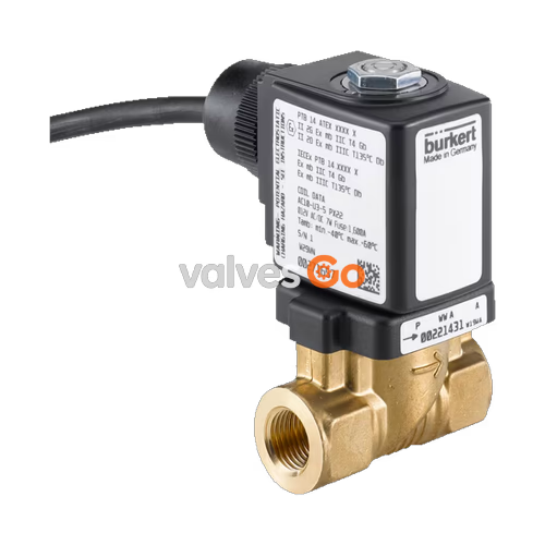
BURKERT 20035150 (Type 6213 EV) is a servo-assisted 2/2-way normally closed diaphragm solenoid valve engineered with a spring-coupled diaphragm system that opens without requiring upstream-downstream differential pressure. Configured as an HP00 variant with a forged brass body complying with DIN EN 50930-6, DN 13 mm orifice, and G 1/2 internal threaded ports, the valve operates across a pressure range of 0.00 to 10.00 bar (PN 10). It is equipped with an integrated Kick and Drop double-coil electronic module operating at 230 to 240 V AC/UC (50/60 Hz), providing high inrush force followed by significant power reduction during steady-state holding.
The valve features certified explosion protection according to ATEX and IECEx standards (Zone 1/21 encapsulation Ex mb), EPDM seat and external seals, and drinking water material conformity under KTW-BWGL. Factory-fitted with a 3.0 m continuous connection cable, unit 20035150 delivers a water flow coefficient (Kv) of 3.6 m³/h and a nominal gas flow rate (QNn) of 3900 l/min, accommodating neutral liquid, gaseous, and vacuum media from -30 °C to +100 °C.
Type 6213 EV operates under circuit function A (normally closed, 2/2-way, de-energized closed). Unlike standard servo-assisted diaphragm valves that require a minimum operating differential pressure of 0.5 bar to open fully, the HP00 execution employs a mechanical spring coupling between the solenoid core and the diaphragm assembly.
Upon coil energization, the core retracts and directly pulls the diaphragm away from the valve seat, allowing media flow even at 0 bar differential pressure. When de-energized, the internal return spring and pilot shut-off mechanism force the diaphragm onto the valve seat. Media flow direction is guided over the seat from inlet port 1 to outlet port 2.
Burkert 20035150 holds European ATEX and international IECEx explosion protection certifications for hazardous dust and gas atmospheres (Category 2, Zones 1 and 21):
The valve also conforms to German UBA assessment principles for materials in contact with drinking water (KTW-BWGL) and relevant European Union CE directives.
Temperature Limit in Hazardous Areas
The maximum medium temperature must never exceed the permitted temperature class minus 5 K: for T4 (+135 °C), maximum medium temperature is +100 °C as limited by the EPDM elastomer; for T5 (+100 °C), maximum medium temperature is +95 °C; for T6 (+85 °C), maximum medium temperature is +80 °C.
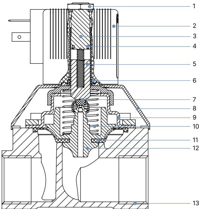
| Item | Component | Material |
|---|---|---|
| 1 | Nut | Steel (thick-film passivated acc. to RoHS) or Stainless steel 1.4305, PTFE-coated |
| 2 | Solenoid Coil | Epoxy (thermal insulation class H) with Kick and Drop electronics |
| 3 | Stopper | Stainless steel 1.4113 |
| 4 | Shading ring | Copper (Cu) for brass body; Silver (Ag) for stainless steel body |
| 5 | Magnetic core | Stainless steel 1.4113 |
| 6 | O-ring | FKM |
| 7 | Plunger seal | EPDM |
| 8 | Bonnet / Protective cover | Polyamide PA6 |
| 9 | Valve cover | Stainless steel 1.4301 (DN 10 to DN 25) |
| 10 | Return spring | Stainless steel 1.4310 |
| 11 | Diaphragm | EPDM |
| 12 | Diaphragm support | PPS GF40 with brass and stainless steel components |
| 13 | Valve body | Brass acc. to DIN EN 50930-6 |
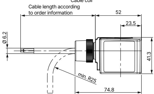
Dimensions for Type 6213 EV HP00 ATEX/IECEx variants with continuous cable outlet:
| Orifice DN [mm] | A [mm] | B [mm] | C [mm] | D [mm] | E [mm] | G Thread F1 [mm] | G Thread G1 | Face-to-Face L [mm] | Wrench Flat SW [mm] |
|---|---|---|---|---|---|---|---|---|---|
| 10 | 71.2 | 82.2 | 36.0 | 45.6 | 22.0 | 12.0 | G 1/4, G 3/8 | 50.0 | 22 |
| 10 | 73.2 | 86.7 | 36.0 | 45.6 | 24.5 | 14.0 | G 1/2 | 55.0 | 27 |
| 13 (20035150) | 82.7 | 96.0 | 44.5 | 56.7 | 27.25 | 14.0 | G 1/2 | 58.0 | 27 |
| 13 | 84.7 | 100.7 | 44.5 | 56.7 | 32.5 | 16.0 | G 3/4 | 65.0 | 32 |
| 20 | 97.2 | 113.2 | 65.0 | 76.6 | 37.0 | 16.0 | G 3/4 | 80.0 | 41 |
| 20 | 99.7 | 120.2 | 65.0 | 76.6 | 37.5 | 18.0 | G 1 | 80.0 | 41 |
Burkert 20035150 incorporates dual-coil Kick and Drop (KD) electronics (coil size 42 mm, code K):
| Parameter | Specification |
|---|---|
| Operating Voltage | 230 to 240 V AC / UC (50/60 Hz) |
| Voltage Tolerance | ±10% |
| Inrush Power (Cold, approx. 500 ms) | 44 W |
| Holding Power (Cold) | 6.5 W |
| Holding Power (Warm) | 5.5 W |
| Permissible Switching Frequency | Max. 6 switching cycles per minute |
| Duty Cycle | 100% ED continuous operation |
| Electrical Connection | 3-core continuous wire cable, 3.0 m length |
| Degree of Protection | IP65 (with cable properly sealed) |
Energy Efficiency and Heat Reduction
The Kick and Drop technology supplies an initial 44 W pulse for 500 ms to overcome diaphragm resistance, then automatically cuts steady-state power down to 5.5 W warm holding. This design reduces coil heat dissipation and prevents medium vaporization in closed fluid loops.

Observe the following mechanical assembly instructions:
Mechanical Strain Hazard
Never use the solenoid coil as a lever arm when threading the valve into piping. Hold the valve body firmly using an open-end wrench across the designated wrench flats (SW 27 mm).
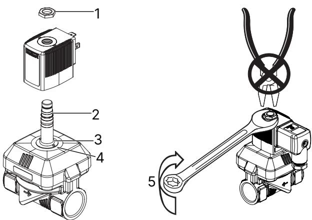
When assembling or servicing the solenoid actuator:
Avoid Over-tightening
Do not continue to rotate firmly fastened nuts past the specified 10 Nm torque limit. Loosening or over-torquing the fixing nut may cause process medium to escape through the core guide tube assembly.
Ordering table for Type 6213 EV HP00 ATEX/IECEx variants with 3 m cable:
| Circuit Function | Port Connection | DN [mm] | Kv (Water) [m³/h] | Pressure Range [bar] | Body Material | Seal Material | Coil Type | 024/UC | 230–240/UC | Weight [kg] |
|---|---|---|---|---|---|---|---|---|---|---|
| CFA (NC) | G 1/2 | 13 | 3.6 | 0–10 | Brass | EPDM | KD Size K | 20051200 | 20051201 / 20035150 | 0.8 |
| CFA (NC) | G 3/4 | 20 | 8.3 | 0–10 | Brass | EPDM | KD Size K | 20051202 | 20051203 | 1.3 |
| CFA (NC) | G 1/2 | 13 | 3.6 | 0–10 | Stainless Steel | FKM | KD Size K | 20031389 | 20051206 | 0.8 |
| CFA (NC) | G 3/4 | 20 | 8.3 | 0–10 | Stainless Steel | FKM | KD Size K | 20046809 | 20051207 | 1.3 |
Explore similar products in our catalog


