

PN16

BURKERT 20043311 (Type 8652 AirLINE) 8-slot valve island with 6 bistable 5/2-way valves, 2 blind plates, Industrial Ethernet (PROFINET/EtherNet/IP/Modbus TCP), aluminium AirLINE Quick plate, and IP20 rating.
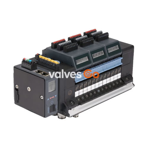
BURKERT 20043311 (Type 8652 AirLINE) is an 8-slot electropneumatic valve island pre-configured for process automation environments. The unit features six 5/2-way bistable impulse solenoid valves (Circuit Function Z) on positions 1 through 6, and two blind plates on positions 7 and 8. It incorporates an anodised aluminium AirLINE Quick adapter plate designed for mounting directly to the control cabinet base or cabinet wall, venting exhaust air and guiding pneumatic connections directly through the cabinet floor.

Fieldbus communication is driven by an integrated Industrial Ethernet interface supporting multi-protocol operations, including PROFINET IO, EtherNet/IP, Modbus TCP, EtherCAT, and CC-Link IE Field Basic over two RJ45 ports (X1 and X2). Local diagnostics are displayed in plain text and symbols on the integrated LC display, and status words are forwarded cyclically to the higher-level PLC. The device operates on 24 V DC and handles operating pressures from vacuum (-1.00 bar) up to 10.00 bar using external auxiliary pilot air (3 to 10 bar).
Article 20043311 is delivered factory-assembled with the following slot population, pneumatic connection fittings, and electrical properties:
| Position / Parameter | Configured Value |
|---|---|
| Valve Slot Count | 8 slots (11 mm station width) |
| Valve Position 1 | 5/2-way bistable solenoid valve (Circuit Function Z, 2 coils, manual override) |
| Valve Position 2 | 5/2-way bistable solenoid valve (Circuit Function Z, 2 coils, manual override) |
| Valve Position 3 | 5/2-way bistable solenoid valve (Circuit Function Z, 2 coils, manual override) |
| Valve Position 4 | 5/2-way bistable solenoid valve (Circuit Function Z, 2 coils, manual override) |
| Valve Position 5 | 5/2-way bistable solenoid valve (Circuit Function Z, 2 coils, manual override) |
| Valve Position 6 | 5/2-way bistable solenoid valve (Circuit Function Z, 2 coils, manual override) |
| Valve Position 7 | Blind plate (dummy valve) |
| Valve Position 8 | Blind plate (dummy valve) |
| Pneumatic Supply Connection (Port 1) | Push-in connector D10 mm, Brass |
| Working Ports (Ports 2 and 4) | Push-in connectors D6 mm, Brass |
| Auxiliary Pilot Air Port | External pilot air feed (3 to 10 bar) |
| AirLINE Quick Adapter Material | Anodised aluminium |
| Additional Intermediate Supply | Without (0 PCE) |
| Digital Input Modules (DI) | None fitted (0 DI) |
| Integrated Check Valves (Ports 3/5) | No |
| Pneumatic HotSwap in Port 1 | No |
| Communication Hardware / Protocol | RJ45 dual-port; Industrial Ethernet (PROFINET IO, EtherNet/IP, Modbus TCP, EtherCAT, CC-Link IE Field Basic) |
| Ingress Protection | IP20 unhoused; IP65 in closed control cabinet with AirLINE Quick plate |
| Parameter | Specification |
|---|---|
| Body Material | PA (Polyamide) |
| Seal Material | NBR and PUR |
| Station Width | 11 mm per valve position |
| Max. Number of Valve Slots (Type 8652 family) | Max. 24 slots (up to 48 controllable valve functions) |
| Operating Medium | Oil-free or lubricated compressed dry air, neutral gases (5 µm filter recommended) |
| Compressed Air Quality | ISO 8573-1:2010, Class 7.4.4 |
| Nominal Operating Pressure Range | Vacuum to 10 bar (-1.00 bar to 10.00 bar) |
| External Auxiliary Pilot Air Range | 3 to 10 bar |
| Nominal Flow Rate $Q_{\text{Nn}}$ (Air) | 310 l/min (measured at +20 °C, 6 bar inlet pressure, 1 bar pressure drop) |
| Nominal Operating Mode | Continuous operation (100% duty cycle) |
| Switching Time (ISO 12238) | Opening: 20 ms, Closing: 25 ms (CF-Z 5/2-way bistable) |
| Operating Voltage | 24 V DC (±10%, residual ripple 1 Vss) |
| Valve Power Consumption | 0.7 W pick-up (0.175 W holding after electronic power reduction) |
| Valve Rated Current | 29 mA pick-up (10 mA holding after electronic power reduction) |
| Protection Class | III according to DIN EN 61140, VDE 0140 |
| Ambient Temperature Range | -10 °C to +55 °C |
| Medium Temperature Range | -10 °C to +55 °C |
| Storage Temperature Range | -20 °C to +60 °C |
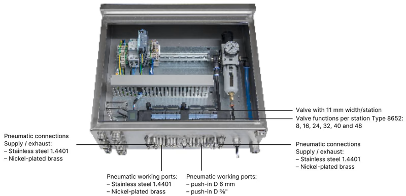
AirLINE Quick eliminates bulkheads and internal distribution piping inside the control cabinet. The adapter plate mechanically seals directly to a cutout in the cabinet floor or side wall, routing all working lines (Port 2 and 4) and exhaust lines (Port 3 and 5) directly outward.
| Feature | Specification |
|---|---|
| Adapter Plate Material | Anodised aluminium (optional: Stainless steel 1.4301) |
| Push-in Fittings Material | Nickel-plated brass (optional: Stainless steel 1.4401) |
| Pneumatic Supply / Exhaust Ports | Push-in connector D10 mm, 3/8" |
| Pneumatic Working Ports | Push-in connector D6 mm, 1/4" |
| Permissible Mounting Locations | Control cabinet floor or control cabinet wall |
Installation Clearance and Cabinet Access
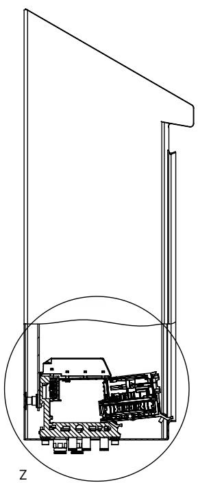
When installing the valve island inside the control cabinet, maintain sufficient clearance between the valve island front edge and the cabinet door/frame. This spacing ensures accessible manual overrides and enables hot-swap removal of individual valve modules without dismounting adjacent units.
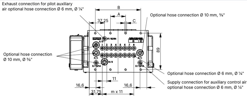
Dimensions for 4-, 8-, and 12-slot configurations according to standard dimensional sheets:
| Variant | A (mm) | B (mm) | C (Fastening Screws) | m | n |
|---|---|---|---|---|---|
| 4-fold | 66 | — | 4 × M5 | 3 | 1 |
| 8-fold (20043311) | 35 | 111 | 8 × M5 | 7 | 2 |
| 12-fold | 77 | 154 | 10 × M5 | 11 | 3 |
Mounting options include direct panel attachment using M5 screws into the AirLINE Quick plate or mounting on standard DIN rails complying with EN 50022 (35 × 7.5 mm or 35 × 15 mm).
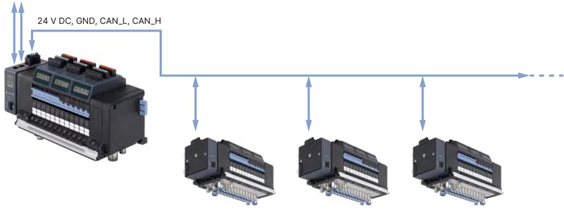
Electrical supply connections are divided into separate logic/display power and pneumatic pilot valve power circuits.
| Pin Position | Terminal Colour | Function / Assignment |
|---|---|---|
| 1 | Red | +24 V DC (Logic and display supply) |
| 2 | White | CAN_H (büS connection) |
| 3 | Green | Shielding |
| 4 | Blue | CAN_L (büS connection) |
| 5 | Black | 0 V DC (GND) |
Permissible conductor cross-section: $\le 1.5\text{ mm}^2$.
| Terminal | Terminal Colour | Function / Assignment |
|---|---|---|
| 1 | Red | AUX +24 V DC (Solenoid coil power) |
| 2 | Black | 0 V DC (GND) |
Pneumatic valve coils must be supplied independently from the communication module via this dedicated 2-pin connector.
| Pin | Signal | Description |
|---|---|---|
| 1 | TX+ | Transmit Data + |
| 2 | TX- | Transmit Data - |
| 3 | RX+ | Receive Data + |
| 4 | N.C. | Not connected |
| 5 | N.C. | Not connected |
| 6 | RX- | Receive Data - |
| 7 | N.C. | Not connected |
| 8 | N.C. | Not connected |
Fieldbus Gateway Module Type ME43
ME43 gateway modules integrated into Type 8652 are unconfigured ex works. Network parameter files (EDS, GSDML, or ESI) must be configured and assigned using Bürkert Communicator software Type 8920 prior to commissioning on the plant network.
Type 8652 supports safety shutdown architectures through optional SIA (Safety-related Interruption Architecture) modules and EVS (External Valve Shutdown) circuits, interrupting pilot coil power independently of fieldbus communication via potential-free mechanical contacts.
Hazardous Area Special Conditions
For installation in hazardous areas classified Zone 2/22 or Class I/II/III Division 2:
| Authority / Type | Certification Code / Standard |
|---|---|
| ATEX Certificate | BVS 20 ATEX E 031 U (II 3G Ex ec IIC Gc / II 3D Ex tc IIIC Dc) |
| IECEx Certificate | IECEx BVS 20.0024 U (Ex ec IIC Gc / Ex tc IIIC Dc) |
| cURus HazLoc (USA / Canada) | Class I, Zone 2, AEx ec IIC Gc / Class II, Zone 22, AEx tc IIIC Dc; Class I, Div 2, Grps A, B, C, D / Class II, III, Div 2, Grps F, G |
| CCC-Ex (China) | GB/T 3836 series compliant for explosion-proof applications in China |
| Electrical Safety | UL 61010-1 / CAN/CSA-C22.2 No. 61010-1 |
| Item Description | Order Article No. |
|---|---|
| Replacement Valve Type 6534: CF-Z 5/2-Way Bistable (24 V DC, 290 l/min, with screws) | 301377 (REF 296034) |
| Replacement Valve Type 6534: CF-C 3/2-Way NC (24 V DC, 270 l/min, with screws) | 20102334 (REF 20088974) |
| Replacement Valve Type 6534: CF-H 5/2-Way Monostable (24 V DC, 290 l/min, with screws) | 301376 (REF 296033) |
| Dummy Valve / Blind Plate (for unused slots) | 335779 (REF 327614) |
| Fieldbus Gateway Module Type ME43: Industrial Ethernet (PROFINET, EtherNet/IP, Modbus TCP, EtherCAT) | 301799 |
| 5-Pin Spring-Loaded Terminal Connector (Logic and display power) | 920180 |
| 2-Pin Spring-Loaded Terminal Connector (Pneumatic valve power) | 920442 |
| Fastening Screw Set M5 × 10 A2 DIN 6912 (10 pcs, cabinet base mounting) | 308661 |
| Height Adapter for 8-Valve Base Plate | 754960 |
| Retaining Plate for 8-Valve Base Plate (cabinet exterior mounting) | 60005566 |
| AirLINE Quick Blind Plate for 8-Valve Base Plate | 754965 |
| USB büS Interface Set 1 (Type 8923, connection to Bürkert Communicator software) | 772426 |
| Bürkert Communicator PC Configuration Software | Type 8920 |
Explore similar products in our catalog


