PN16

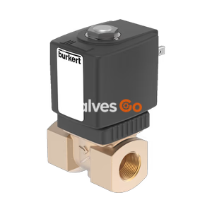
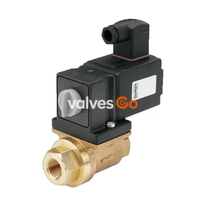
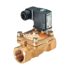
BURKERT 20045495 Type 6281 servo-assisted 2/2-way NC solenoid valve insert (DN20, Kv 8.5 m³/h) features 24V DC operation, EPDM seals, 0.2-16 bar operating pressure, and ATEX/IECEx Zone 2/22 approvals.
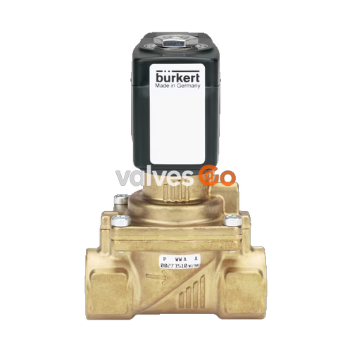
BURKERT 20045495 (Type 6281) is a servo-assisted 2/2-way plunger-actuated solenoid valve assembly designed for normally closed (Circuit Function A) operation. Supplied in a "without fluidic body" configuration for system-internal manifold integration or replacement onto existing DN20 brass valve bodies, it features a 20 mm main orifice, a 1.3 mm pilot control bore, and an operating pressure range of 0.20 bar to 16.00 bar. Operating on a 24 V DC power supply with 8 W warm holding power (9.5 W cold), the unit is sealed with ethylene-propylene diene rubber (EPDM), accommodating media temperatures from -30 °C to +100 °C, delivering a water flow factor (Kv) of 8.5 m³/h and a gas flow rating (QNn) of 9,100 l/min.
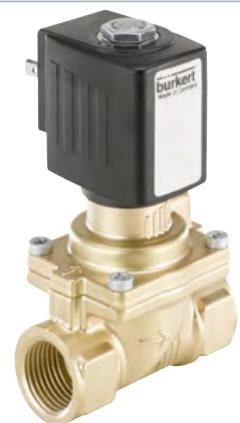
Type 6281 operates as a servo-assisted diaphragm valve. A minimum differential pressure of 0.2 bar between the pressure inlet and outlet is necessary to initiate movement, while a differential pressure of 0.5 bar is required to open the complete 20 mm cross-section. The internal pilot mechanism routes media through the 1.3 mm pilot seat via the armature, allowing process pressure to lift the diaphragm from the primary valve seat.
The actuator utilizes a vibration-resistant, centrally screwed coil system. Internal damping mechanisms control closing velocity to mitigate fluid pressure surges and minimize closing noise during cycling. Article 20045495 does not include a manual override, ensuring switching remains under electrical pilot control.
| Parameter | Value |
|---|---|
| Article Number | 20045495 |
| Type | 6281 (EV Generation) |
| Circuit Function | A (2/2-way, normally closed, pressure port 1 P/NC) |
| Main Valve Orifice (DN) | 20 mm (3/4") |
| Pilot Control Orifice | 1.3 mm |
| Flow Rate Kv (Water) | 8.5 m³/h |
| Flow Rate QNn (Gas) | 9,100 l/min |
| Operating Pressure Range | 0.20 bar to 16.00 bar (PN16) |
| Operating Voltage | 24 V DC (tolerance ±10%) |
| Power Consumption | 9.5 W (cold) / 8 W (warm) |
| Duty Cycle | 100% ED continuous operation |
| Switching Time (Opening) | 0.1 s to 1.5 s (at +20 °C, 6 bar inlet) |
| Switching Time (Closing) | 0.2 s to 4.0 s (at +20 °C, 6 bar inlet) |
| Medium Temperature Range | -30 °C to +100 °C |
| Ambient Temperature Range | -40 °C to +60 °C (standard service maximum +55 °C) |
| Valve Construction | Without fluidic body (system-internal integration) |
| Media-Contacting Body Material | Brass (DIN EN 50930-6 compatible) |
| Seat & External Seals | EPDM (ethylene-propylene diene rubber) |
| Electrical Connection | Plug pattern Form A acc. to DIN EN 175301-803 (cable plug enclosed) |
| Degree of Protection | IP65 with mounted cable plug |
| Explosion Protection | II 3 G Ex ec IIC T4 Gc / II 3 D Ex tc IIIC T135°C Dc |
| Drinking Water Approval | KTW-BWGL (material approval) |
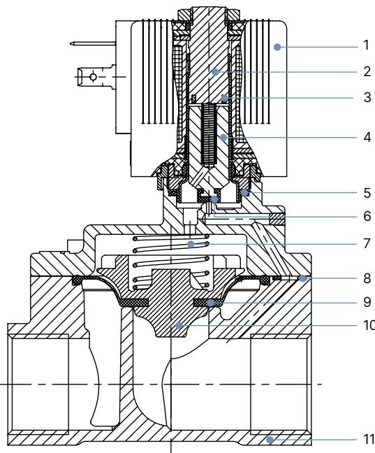
| Item | Component | Material |
|---|---|---|
| 1 | Solenoid Coil | Polyamide / Epoxy |
| 2 | Stopper | Stainless steel 1.4113 |
| 3 | Shading Ring | Copper (Cu) |
| 4 | Magnetic Core (Plunger) | Stainless steel 1.4113 |
| 5 | O-Ring | EPDM |
| 6 | Core Seal | EPDM |
| 7 | Core Spring | Stainless steel 1.4310 |
| 8 | O-Ring | EPDM |
| 9 | Diaphragm | EPDM |
| 10 | Diaphragm Holder | PPS GF40 |
| 11 | Valve Body Interface | Brass acc. to DIN EN 50930-6 |
EPDM seals permit operation with cold and hot water as well as oil-free and fat-free fluids across -30 °C to +100 °C. The sealing formulation complies with German Federal Environment Agency (UBA) KTW-BWGL assessment principles for drinking water contact.
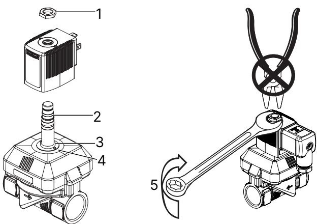
Article 20045495 is supplied without an external threaded valve body. When installing this pilot and diaphragm module into an internal machine block or a replacement brass housing:
Pressure Hazard
Before loosening any line fittings, retaining screws, or the core guide assembly, completely depressurize and vent all connected supply lines.
Solenoid Overheating Risk
Do not connect the solenoid coil to electrical power when it is detached from the armature and core tube. Energizing an unmounted coil causes immediate magnetic saturation, resulting in rapid thermal overload and coil failure.
Continuous Operation
The coil is rated for 100% ED continuous service. If the valve remains inactive during extended system downtime, execute at least 1 to 2 test cycles daily to prevent core binding.
Electrical connection is established through an enclosed cable plug compliant with DIN EN 175301-803 Form A. Tighten the central plug screw to a maximum torque of 1 Nm. Verify that the flat rubber perimeter gasket is seated evenly between the plug base and coil terminal block to maintain the IP65 ingress rating.
Connect the 24 V DC power supply conductors to terminal 1 and terminal 2. Always connect the external protective earth conductor to the PE terminal and verify electrical ground continuity between the coil enclosure and the mating metal body.
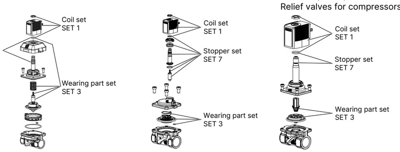
If the valve fails to switch, inspect the system according to the following criteria:
Original Bürkert wear sets (SET 1, SET 3, SET 7) can be ordered by quoting device article number 20045495.
Explore similar products in our catalog