PN16

BURKERT 20046099 (Type 6014) is a direct-acting 3/2-way banjo solenoid valve featuring G 1/4 ports, DN 2.0 orifice, PPS body, FKM seals, manual override, and 3 m potted cable with ATEX/IECEx Ex mb T4 certification.
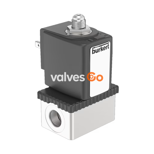
BURKERT 20046099 (Type 6014) is a direct-acting 3/2-way plunger solenoid valve engineered for direct mounting onto pneumatic valves and actuators using a G 1/4 banjo bolt connection. The valve features a 2.0 mm (5/64 inch) orifice, an operating pressure span from 0 to 10 bar, a polyphenylene sulphide (PPS) valve body, and FKM fluororubber seals. Actuation is driven by an encapsulated AC10 solenoid coil certified under ATEX and IECEx standards for explosion protection class Ex mb, supplied via an integrated 3-meter potted connection cable.
Equipped with a built-in emergency manual override, BURKERT 20046099 permits manual operation during commissioning, fault diagnosis, or electrical power interruptions. The core guide tube and stopper are welded together to enhance internal pressure containment and seal integrity under mechanical and thermal strain, maintaining tight isolation across neutral gas, technical vacuum, and liquid media.
BURKERT 20046099 operates in circuit function C (CF C), configured as a direct-acting 3/2-way valve that remains closed in the de-energised position.
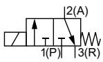
In the de-energised state, pressure port 1 (P/NC) is closed, while outlet port 2 (A/OUT) is connected to exhaust port 3 (R/NO). Upon electrical energisation, the plunger lifts to open the flow path from pressure port 1 (P) directly to outlet port 2 (A), sealing off the exhaust port 3 (R). Fluid flow direction is directed from 1 (P) to 2 (A).
Single Mounting Specification
Article 20046099 is configured with an Ex mb potted cable coil rated for single valve mounting across an ambient operating temperature range of -10 °C to +55 °C.
| Specification Parameter | Technical Value |
|---|---|
| Valve Type | 6014 |
| Article Number | 20046099 |
| Circuit Function | C (3/2-way, direct-acting, normally closed) |
| Orifice Size (DN) | 2.0 mm (5/64") |
| Flow Factor Kv (Water, +20 °C) | 0.086 m³/h |
| Operating Pressure Range | 0.00 to 10.00 bar (liquid and gas) |
| Port Connection 1 (P) | Banjo G 1/4 |
| Port Connection 2 (A, Banjo Bolt) | G 1/4 (76 mm hollow screw) |
| Port Connection 3 (R, Exhaust) | Threaded exhaust port |
| Valve Body Material | PPS (polyphenylene sulphide) |
| Seat & External Seal Material | FKM (fluororubber) |
| Nominal Voltage | 24 V AC/DC (UC, 50/60 Hz) |
| Electrical Power Consumption | 9 W (Coil size 6, 40 mm) |
| Response Time (Opening) | 10 to 15 ms |
| Response Time (Closing) | 15 to 20 ms |
| Maximum Fluid Viscosity | 21 mm²/s |
| Medium Temperature Range | -10 °C to +120 °C |
| Permissible Ambient Temperature | -10 °C to +55 °C |
| Electrical Connection Type | Moulded cable, 3-wire, length 3,000 mm |
| Enclosure Protection Rating | IP65 |
| Manual Override | Rotary emergency manual override integrated |
BURKERT 20046099 is certified for operation in hazardous areas according to European ATEX Directive and international IECEx scheme specifications for Category 2 equipment (Zones 1 and 21).
Ex mb)Hazardous Area Safety Notice
In potential explosive atmospheres, the valve must remain completely assembled during operation. Disconnecting or opening the coil and valve while energised creates an explosion risk. Do not expose the cable to tensile loads, sharp edges, or temperatures above allowable operational limits. Clean surfaces only with a damp or antistatic cloth to prevent electrostatic discharge.
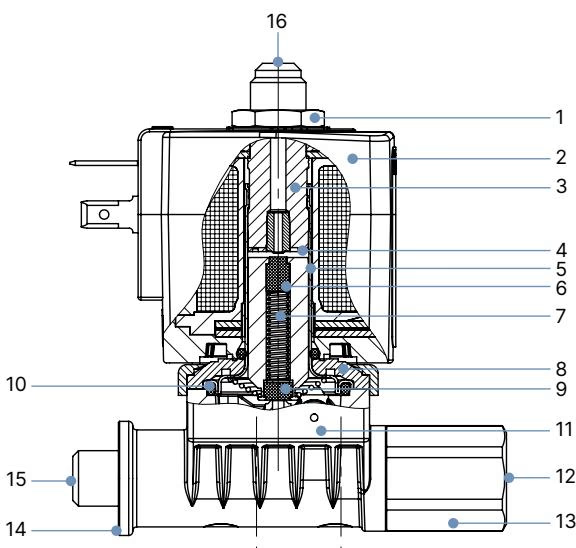
| Item No. | Component Name | Material Specification |
|---|---|---|
| 1 | Retaining Nut | Steel, surface thick-film passivated |
| 2 | Solenoid Coil Housing | Epoxy encapsulation (Ex m variant) |
| 3 | Stopper | Stainless steel 1.4105 / AISI 430F |
| 4 | Shading Ring | Copper (Cu) |
| 5 | Core Guide Tube | Stainless steel 1.4303 / AISI 305 / 308 |
| 6 | Magnetic Core / Plunger | Stainless steel 1.4105 / AISI 430F |
| 7 | Return Spring | Stainless steel 1.4310 / AISI 301 |
| 8 | Sub-base / Flange Plate | Steel, surface thick-film passivated |
| 9 | Plunger Seal | FKM (fluororubber) |
| 10 | O-Rings | FKM (fluororubber) |
| 11 | Valve Body | PPS (polyphenylene sulphide) |
| 12 | Pressure Connection P | G 1/4 internal thread |
| 13 | Banjo Hollow Screw | Brass (76 mm length) |
| 14 | Banjo Sealing O-Rings | FKM (fluororubber) |
| 15 | Working Connection A | G 1/4 external banjo interface |
| 16 | Exhaust Port R | Exhaust connection |
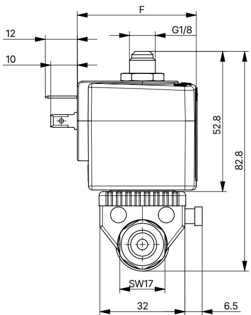
The banjo configuration BJ02 utilizes a 76 mm hollow bolt connecting directly into the pilot port of a pneumatic actuator.
Banjo Bolt Installation
When mounting the banjo body onto pneumatic equipment, inspect the FKM sealing rings positioned at the hollow bolt shoulder and body interface. Ensure alignment of the internal cross-drilling with the fluid flow passage before tightening to specified mounting torque.
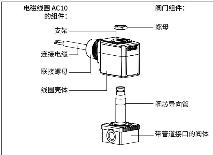
The AC10 solenoid coil integrates a permanently potted 3-core polyolefin cable exiting perpendicular to the coil axis. The cable has an outer diameter of 6.2 mm, a minimum bending radius of 4 times the outer diameter for fixed routing, and is halogen-free in compliance with IEC 60754-1.
| Conductor Wire Color | Pin Assignment & Polarity |
|---|---|
| Green-Yellow | Protective Earth Conductor (PE) |
| Black Conductor 1 | Neutral Conductor / Cathode (-) |
| Black Conductor 2 | Phase / Anode (+) |
Protective Grounding Requirement
Always connect the green-yellow protective conductor to the plant equipotential bonding system. The coil internal construction provides continuity between the protective earth wire and the core guide tube, grounding all exposed metallic components of the valve.
Explore similar products in our catalog