PN16

BURKERT 20050987 (Type 8640) modular valve island for pneumatics. Features 11mm width per station, mixed valve population, G 1/4 pressure port, and IP20 protection.
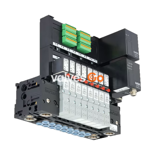
BURKERT 20050987 (Type 8640) is a modular valve island for pneumatics. The Type 8640 valve unit system is designed to solve diverse and complex control problems due to its systematic modular construction and combination of pneumatic and electrical interfaces. By putting together a row of pneumatic modules with different numbers of valves, 2 to 24 valve functionalities may be realized on one valve unit. Electrical connectivity is achieved by either fieldbus interfaces, common connection (parallel connection technique) or multipin interfaces. Bodies and connection modules are made of high-quality plastic (polyamide) and are easy to assemble by means of the built-in snap connectors.

| Product properties | Type 0460, Type 6524, Type 6525 (11 mm) |
|---|---|
| Body Material | PA (polyamide), aluminium (Type 0460) |
| Seal Material | FKM, NBR and PUR |
| Width per station | 11 mm |
| Manual override | Standard |
| Number of valve slots | Max. 24 (Max. 12 for impulse and double valves) |
| Pressure range | Vac...10 bar |
| Operating voltage | 24 V DC (±10% tolerance) |
| Degree of protection | IP20 (IP65 in closed control cabinets) |
| Working port | D 6, D 1/4 |
| Air supply connection 1 (P), 3 (R), 5 (S) | G 1/4, D 3/8 |
| Ambient temperature | 0 °C...+ 55 °C (when using Type 0460: 0 °C...+ 50 °C) |
The pneumatic basic and connection modules have been optimised in the REV3 generation. The 20050987 model is a REV3 configuration.
| Feature | Type 8640 REV3 |
|---|---|
| Visual distinction 11 mm | 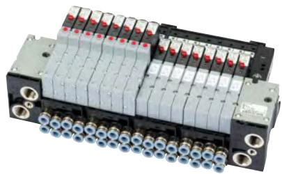 |
| Channel arrangement of the working connections | Wavy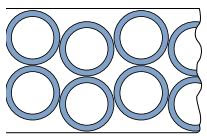 |
| Colour of the release rings (hose connector) | Blue |
| Flow reduction with integrated P shut-off | Up to 20 % |
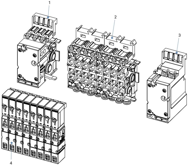
| No. | Element |
|---|---|
| 1 | Pneumatic connection module, left |
| 2 | Basic pneumatic modules |
| 3 | Pneumatic connection module, right |
| 4 | Valves (for example 5/2-way) |
WARNING
Risk of injury due to unintentional activation of the system and uncontrolled restart.
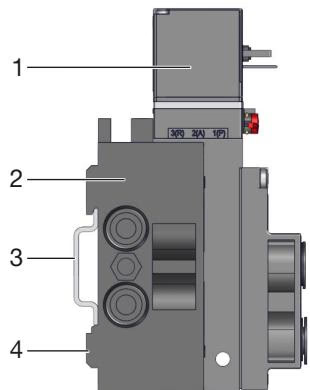
Standard rail installation:
Wall installation: Fasten the valve block directly to the wall with M4 screws.
DANGER
Risk of injury due to high pressure and escaping medium.
Before connection:
Pneumatic connection:
Requirements for hose lines:
Ensure that the appropriate combination of hose material (polyamide or polyurethane) and push-in connector is used, as different materials require different holding forces. Press the hose into the push-in connector with sufficient force. The hose must be inserted deep enough into the push-in connector so that it is held correctly by the claws.
Minimum tensile force for the tensile test (DIN ISO 14743:2020):
| Hose OD, D, mm | 3 | 4 | 6 | 8 | 10 | 12 | 16 |
|---|---|---|---|---|---|---|---|
| Minimum tensile force for polyamide hose (PA), N | 60 | 70 | 120 | 170 | 250 | 300 | 350 |
| Minimum tensile force for polyurethane hose (PU), N | 25 | 50 | 100 | 150 | 200 | 200 | 300 |
Explore similar products in our catalog