


Up to 99.8% Efficiency

Burkert 20051631 (Type 3361) is a 2-way electromotive globe control valve with G 1 connection, PEEK seat, 15 mm orifice, 24 V DC AG2 actuator, SAFEPOS energy pack, and integrated analogue positioner.
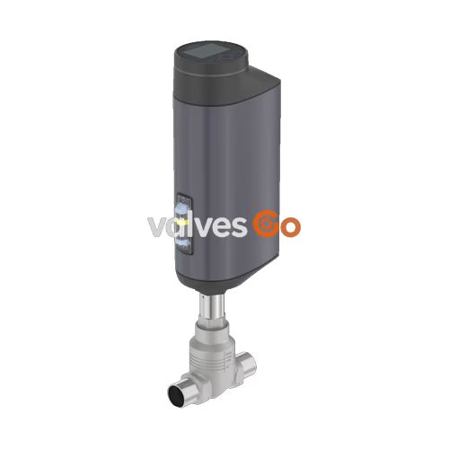
BURKERT 20051631 is an electromotive 2-way globe control valve belonging to Type 3361, engineered for continuous, dynamic flow control under demanding chemical, process, and hygienic operational conditions. Powered by a 24 V DC supply, this specific assembly integrates a cast stainless steel CF3M valve body with G 1 internal thread connections (DN 25) and an AG2 linear electromotive actuator generating 1,300 N of positioning thrust. A precision ground ball screw translates motor rotation into a 6 mm/s linear stem displacement without slip or back-drive, maintaining steady plug positioning despite process pressure fluctuations. With an orifice seat diameter of 15 mm and a PEEK soft seat seal, this valve achieves DIN EN 60534-4 Leakage Class VI bubble-tight shut-off across an operating pressure span from 0 to 25 bar. Media travels below the valve seat with an equal percentage flow profile (50:1 theoretical rangeability) and a nominal capacity rating of Kvs 5.3 m³/h (Cv 6.2 gpm). The assembly incorporates an internal SAFEPOS energy-pack storage module, driving the valve to a normally opened (NO) fail-safe position upon line voltage failure.
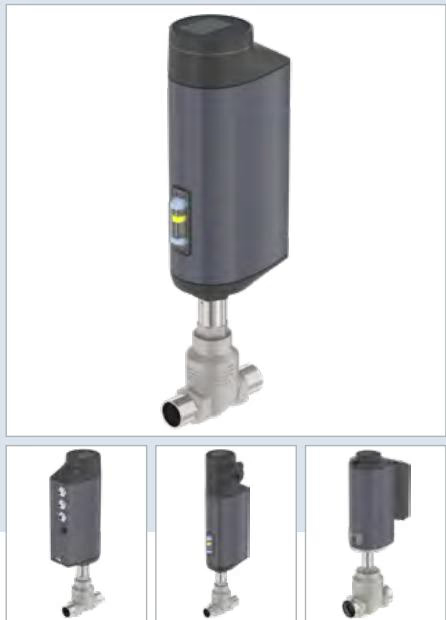
Operating performance conforms to DIN EN 60534 standards for industrial process control valves. Actuator force, timing, and environmental limits are detailed below:
| Parameter | Specification |
|---|---|
| Valve Type | Type 3361 electromotive 2-way globe control valve |
| Article Number (MPN) | 20051631 |
| Nominal Diameter (Port) | DN 25 (NPS 1) |
| Port Connection Type | G 1 internal thread (DIN ISO 228-1) |
| Seat Diameter (Orifice) | 15 mm (9/16") |
| Flow Coefficient (Kvs) | 5.3 m³/h (water at +20 °C) |
| Theoretical Rangeability | 50:1 (equal percentage curve) |
| Flow Direction | Below seat (marked 2 → 1 on body) |
| Operating Pressure Range | 0 to 25 bar(g) |
| Nominal Pressure Class | PN 25 (DIN EN 1333), Class 150 (DIN EN 1759) |
| Medium Temperature Range | -10 °C to +185 °C |
| Ambient Temperature Range | -25 °C to +65 °C (derating curves apply at high fluid temperatures) |
| Fluid Viscosity | Up to 600 mm²/s |
| Operating Voltage | 24 V DC ±10% (maximum residual ripple 10%) |
| Current Consumption | Maximum 3 A at peak mechanical load (includes 1 A SAFEPOS charging current); +2 A at minimum operating temperature |
| Standby Power | 2 to 5 W |
| Positioning Speed | 6 mm/s |
| Typical Closing Time | 3.3 s |
| Deadband (Positioning) | ±0.1% |
| Duty Cycle | 100% continuous |
| Fail-Safe Energy Return | Integrated SAFEPOS energy-pack (normally opened delivery setting) |
| Protection Class | Class III (DIN EN 61140) |
| Enclosure Rating | IP65 / IP67 (DIN EN 60529), NEMA 4X |
| Conformity & Certification | Regulation (EC) No 1935/2004, Ecolab detergent resistance (F&E/P3-E No. 40-1) |
The closed actuator housing and smooth exterior surfaces resist atmospheric corrosion, mechanical impacts, and washdown chemicals.
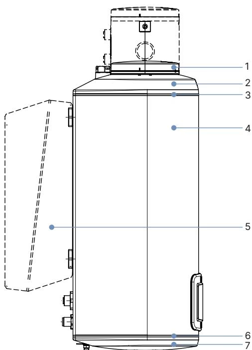
| Item No. | Actuator Component (AG2) | Material |
|---|---|---|
| 1 | Blind cover / dummy cover | PPS (Polyphenylene sulphide) |
| 2 | Actuator cover | PPS |
| 3, 6 | O-ring seals | EPDM |
| 4 | Actuator main housing | Powder-coated aluminium |
| 7 | Actuator base | PPS |
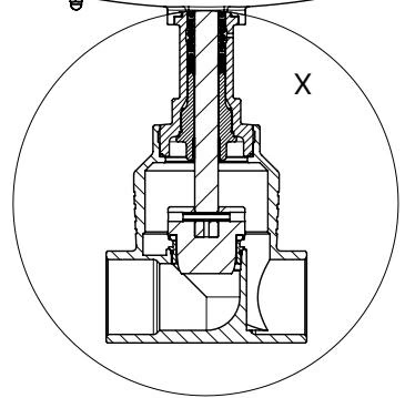
| Item No. | Valve Body & Trim Component | Material |
|---|---|---|
| 1 | Spindle (Stem) | Stainless steel 1.4401 (316) / 1.4404 (316L) |
| 2 | Spindle packing seal | PTFE V-rings (filled) with stainless steel spring compensation |
| 3 | Spindle guide | Stainless steel 1.4404 (316L) |
| 4 | Packing gland tube | Stainless steel 1.4401 (316) |
| 5 | Body gasket seal | Graphite or PTFE |
| 6 | Valve seat seal | PEEK (Polyetheretherketone) seal disc |
| 7 | Control cone | Stainless steel 1.4571 (316Ti) |
| 8 | Screwed-in valve seat | Stainless steel 1.4571 (316Ti) |
| 9 | Valve seat O-ring | EPDM or PTFE |
| 10 | Valve body | Stainless steel CF3M (cast 316L equivalent) |
BURKERT 20051631 comprises an AG2 actuator atop a DN 25 G 1" threaded globe body. Dimensions below are expressed in millimeters.
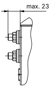
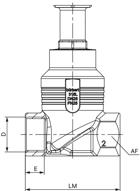
| Dimension | Description | DN 25 (G 1") Value |
|---|---|---|
| H1 | Actuator height above pipe centerline (standard blind cover) | 446 mm |
| H2 | Actuator height with integrated fieldbus gateway module | 518 mm |
| D | Port connection thread size | G 1 (DIN ISO 228-1) |
| E | Thread engagement depth | 18 mm |
| LM | Valve body face-to-face installation length | 90 mm |
| AF | Width across flats on pipe ports | 41 mm |
In the fully seated closed position, the actuator raises an additional 2 mm when adjusting without tight seating function.
Electrical connections interface through standard industrial M12 connectors located on the side of the AG2 actuator base.
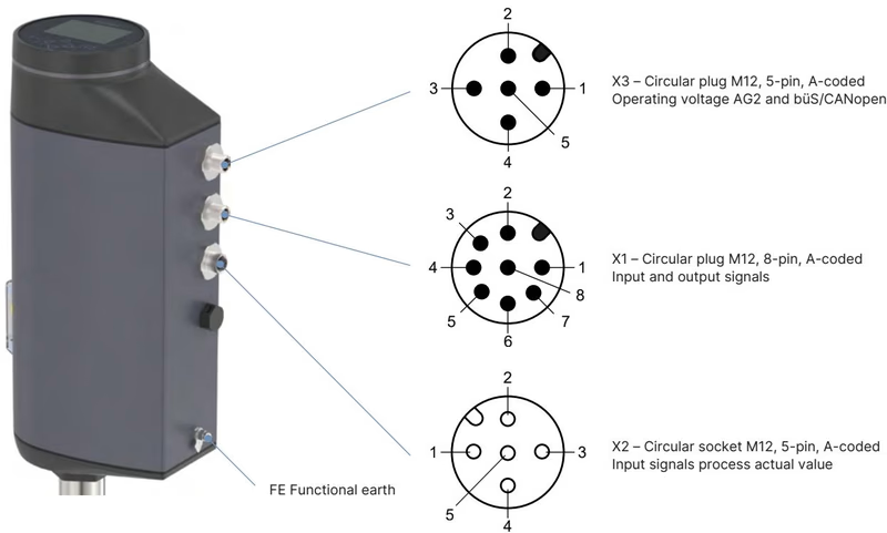
| Connector Identifier | Connector Format | Description |
|---|---|---|
| X1 | M12 male plug, 8-pin, A-coded | Analogue/digital input and output control signals |
| X3 | M12 male plug, 5-pin, A-coded | 24 V DC power supply and büS/CANopen communication |
| Pin No. | Signal Assignment |
|---|---|
| 1 | Digital input + (10 to 30 V DC = High, 0 to 5 V DC = Low) |
| 2 | GND reference for digital input and digital outputs |
| 3 | Digital output 2 + (PNP, max. 100 mA) |
| 4 | Digital output 1 + (PNP, max. 100 mA) |
| 5 | Analogue output - (galvanically isolated) |
| 6 | Analogue output + (0/4 to 20 mA, max. 800 Ω load; or 0 to 5/10 V, max. 10 mA) |
| 7 | Setpoint / analogue input - |
| 8 | Setpoint / analogue input + (0/4 to 20 mA at 70 Ω, or 0 to 5/10 V at 22 kΩ) |
| Pin No. | Signal Assignment |
|---|---|
| 1 | CAN shield / cable shield |
| 2 | Operating voltage +24 V DC (±10%) |
| 3 | GND / CAN_GND |
| 4 | CAN_H (büS communication line) |
| 5 | CAN_L (büS communication line) |
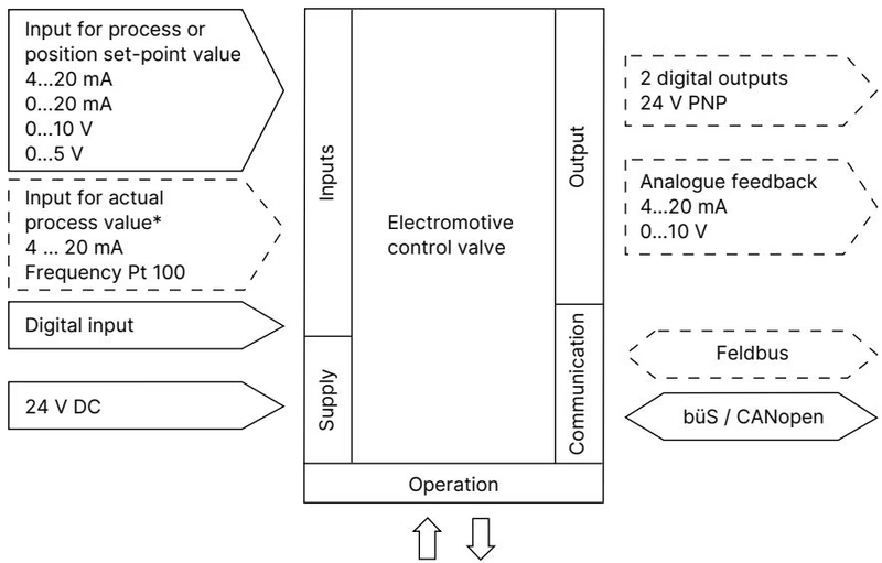
The valve features an equal percentage flow profile conforming to DIN EN 60534-2-4. Water flow capacity across stroke progression for seat size 15 mm in a DN 25 body is given below:
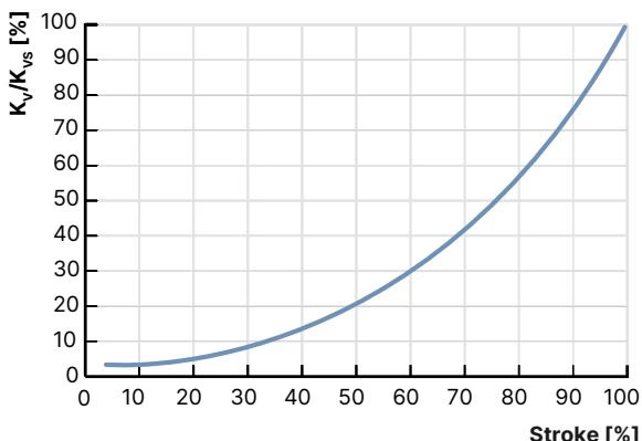
| Stroke (%) | Kv Value (m³/h) |
|---|---|
| 5% | 0.14 |
| 10% | 0.17 |
| 20% | 0.22 |
| 30% | 0.35 |
| 40% | 0.52 |
| 50% | 0.80 |
| 60% | 1.2 |
| 70% | 1.8 |
| 80% | 2.9 |
| 90% | 4.0 |
| 100% (Kvs) | 5.3 (Cv 6.2 gpm) |
The KvR value represents the lowest flow coefficient at which the profile tolerance complies with DIN EN 60534-2-4. For seat sizes greater than 10 mm, KvR is evaluated at 5% stroke.
Permissible line pressure depends on fluid temperature in accordance with DIN EN 12516-1 (PN 25) and ASME B16.34 (Class 150). For a PEEK soft seal, temperature boundaries and leakage ratings compare against alternate seat options as follows:
| Seat Material | Tight Sealing Required | Seat Leakage Class (DIN EN 60534-4) | Permissible Medium Temperature | Application Recommendations |
|---|---|---|---|---|
| Stainless steel 1.4571 | No | Class III / IV | -40 °C to +230 °C | Permissible leakage 0.1% to 0.01% of nominal flow. Impervious to cavitation and abrasive particles. |
| Hardened stainless steel | No | Class III / IV | -40 °C to +230 °C | For extreme erosion, high velocities, and wet steam throttling. |
| PTFE | Yes | Class VI | -40 °C to +130 °C | Bubble-tight soft seal; recommended for applications up to +130 °C. |
| PEEK (20051631) | Yes | Class VI | -10 °C to +185 °C (rated to +230 °C in dry heat) | Bubble-tight closure. Recommended for elevated temperatures above +130 °C. |
Ambient Temperature Derating
At maximum medium temperatures of +185 °C, the permissible ambient operating temperature must be derated according to the AG2 thermal limit curves. For units fitted with the SAFEPOS energy-pack, high ambient exposure combined with continuous motor duty reduces internal capacitor service life.
Position control operates as a closed loop utilizing an internal non-contact displacement transducer.
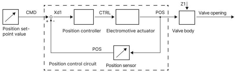
An external analogue setpoint CMD (0/4–20 mA or 0–5/10 V) is continuously compared against the measured stem stroke POS. If a deviation Xd1 exists, motor controller CTRL modulates the brushless motor to align position with a deadband accuracy of ±0.1%.
Local configuration on 20051631 is managed via four DIP switches and two push buttons positioned under the plastic blind cover:
The integrated SAFEPOS storage unit consists of high-reliability supercapacitors designed for automated fail-safe operation:
When electrical supply is disconnected, the valve position can be adjusted using the mechanical manual override located beneath the blind cover.
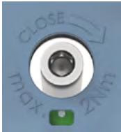
Mechanical Override Precautions
Actuate the mechanical override only when the supply voltage is disconnected and the SAFEPOS energy-pack is completely discharged. Never apply more than 2 Nm torque to the 3 mm hex socket; exceeding this limit damages internal gears.
Routine maintenance covers replacement of the control cone, spindle chevron packing seals, and the threaded valve seat ring.
Adhere strictly to factory assembly torques during reassembly:
Commissioning with X.TUNE
After replacing the valve seat, control cone, or seal set, calibrate the positioner by running the automatic X.TUNE function:
| Accessory Description | Order Number |
|---|---|
| Replacement SAFEPOS energy-pack (AG2) | 285834 |
| SIM card for device parameter backup | 291773 |
| M12 female socket with 5 m cable, 4-pin, A-coded (X3 power supply) | 918038 |
| M12 female socket with 2 m cable, 8-pin, A-coded (X1 signal interface) | 919061 |
| USB büS-Interface Set 1 (includes power supply, büS stick, terminating resistor, Y-splitter, 0.7 m cable) | 772426 |
| büS adapter cable (M12 to Micro-USB service interface, 0.3 m) | 774931 |
| Valve seat installation wrench for DN 25 | 652606 |
| Modified packing gland socket wrench (SW21, 14 mm spindle) | 683223 |
| Holding device for pipe sizes DN 25 to DN 50 | 693771 |
Explore similar products in our catalog


