PN16

Burkert 20053556 Type 8640 modular valve island for pneumatics. Features a 33mm 3-bank setup, G 1/2 pressure port, 2-8 bar operating pressure, and DIN-rail mounting.
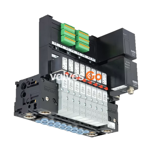
The BURKERT 20053556 Type 8640 is a modular valve island designed to solve diverse and complex control problems due to its systematic modular construction and combination of pneumatic and electrical interfaces. This specific 33mm 3-bank valve block features a G 1/2 pressure port, G 1/4 working ports, and operates within a 2 to 8 bar pressure range. By putting together a row of pneumatic modules, multiple valve functionalities may be realized on one valve unit. Bodies and connection modules are made of high-quality plastic (polyamide) and are easy to assemble by means of built-in snap connectors.

| Property | Value |
|---|---|
| Add-on dimension | 33 mm |
| Pressure port | G 1/2 |
| Working port | G 1/4 |
| Working connection position | Opposite of supply side |
| Nominal pressure | 2 to 8 bar |
| Temperature medium | 0 °C to 50 °C |
| Temperature environment | 0 °C to 55 °C |
| Mounting type | DIN-rail installation |
| Protection type | IP20 |
Safety Warnings
Risk of injury due to high pressure and escaping medium.
Risk of injury due to electric shock.
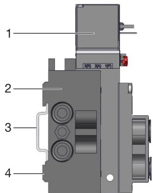
Standard rail installation:
Wall installation:
WARNING
Risk of injury from quickly accelerating device parts and unconnected compressed air hoses flapping around.
Before connection:
Pneumatic connection:
INFO
Breaking hazard: Do not use the coil as a lever arm. Do not use a pipe wrench when screwing in.
Explore similar products in our catalog