

PN16

BURKERT 20053828 (Type 8640 REV3) is a 16.5 mm modular valve block with G 3/8 supply ports and bottom push-in D8 working ports, operating at 2-10 bar with single wiring, 24 V DC, and DIN-rail mounting.
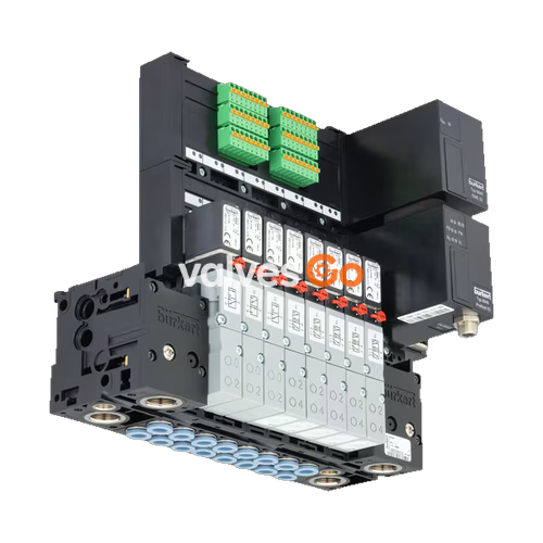
BURKERT 20053828 is a Type 8640 Revision 3 (REV3) modular pneumatic valve island configured for 16.5 mm station width installations. Designed for complex process pneumatic automation tasks, the assembly integrates pneumatic base modules and pilot-operated valves into a continuous manifold block. Air supply connection 1 (P) and exhaust ports 3 (R) and 5 (S) are sized at G 3/8, providing centralized fluid distribution across all mounted stations. Working ports 2 (A) and 4 (B) feature D8 push-in connectors positioned at the bottom of the pneumatic module, facilitating straight drop line routing within control cabinets.
Operating across a pressure range of 2.00 to 10.00 bar, the 20053828 assembly supports media temperatures from 0 °C to +50 °C and ambient temperatures up to +55 °C. The unit operates with individual electrical wiring (single wiring), omitting internal fieldbus communication modules to deliver direct point-to-point electrical control. Mechanical installation is pre-configured for standard DIN rail mounting in accordance with EN 50022.
| Specification Parameter | Technical Value |
|---|---|
| Manufacturer SKU / Article Number | 20053828 |
| Valve Island Type | Type 8640 Generation Revision 3 (REV3) |
| Station Grid Width | 16.5 mm per station |
| Valve Population Type | Mixed valve population (3/2-way and 5/2-way pilot valves) |
| Pneumatic Supply / Exhaust Ports (1, 3, 5) | G 3/8 threaded ports |
| Pneumatic Working Ports (2, 4) | Push-in connector D8 (∅ 8 mm) |
| Working Port Orientation | Bottom outlet (pneumatic base module) |
| Operating Pressure Range | 2.00 bar to 10.00 bar (overpressure to atmospheric) |
| Medium Temperature Range | 0.00 °C to +50.00 °C |
| Ambient Operating Temperature | 0.00 °C to +55.00 °C |
| Storage Temperature Range | -20 °C to +60 °C |
| Operating Medium | Oil-free or lubricated compressed dry air, neutral gases (ISO 8573-1: 2010 Class 7.4.4, 5 µm filter recommended) |
| Station Flow Rate (QNn air) | 700 l/min (at +20 °C, 6 bar inlet pressure, 1 bar differential pressure) |
| Nominal Duty Cycle | Continuous operation (100% ED) |
| Electrical Control Architecture | Single wiring / collective connection (without internal bus) |
| Digital Input Count | 0 PCE |
| Operating Voltage | 24 V DC (±10% permissible tolerance, residual ripple 1 Vss) |
| Valve Power Consumption | 1 W or 2 W (depending on installed pilot valve) |
| Degree of Protection | IP20 (DIN EN 60529 / IEC 60529); IP65 in closed control cabinet |
| Protection Class | III according to VDE 0580 |
| Body / Module Material | Polyamide (PA) |
| Seal Material | Nitrile butadiene rubber (NBR) |
| Mounting Execution | DIN-rail installation (EN 50022 35 x 7.5 or 35 x 15) |
Type 8640 REV3 pneumatic assemblies use interlocking modular elements molded from polyamide. Individual valve positions are established by combining supply connection units, intermediate basic pneumatic blocks, and right-hand connection modules held securely by built-in latch tabs and latch hooks.
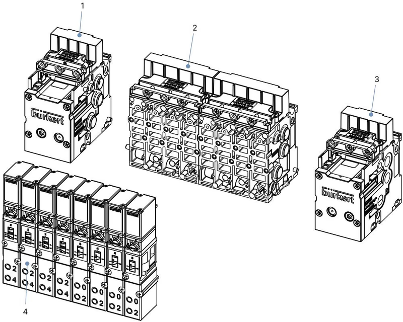
| Item Number | Module Designation | Function and Characteristics |
|---|---|---|
| 1 | Pneumatic connection module, left | G 3/8 collective supply port 1 (P) and exhaust ports 3 (R), 5 (S) |
| 2 | Basic pneumatic modules (4-fold) | 16.5 mm grid modules with bottom D8 push-in connections and FM17 valve interface |
| 3 | Pneumatic connection module, right | Closes internal air channels or accommodates secondary pressure stage feeds |
| 4 | Solenoid valves | Type 6526 (3/2-way) or Type 6527 (5/2-way) pneumatic pilot valves |
Revision 3 Identification
Type 8640 REV3 pneumatic modules are visually distinguished by blue release rings on the push-in connectors and a wavy channel arrangement for the working connections, compared to the straight parallel layout and black rings of legacy REV1/REV2 blocks. Flow reduction through integrated P-shut-off elements is limited to a maximum of 20% on REV3 assemblies.
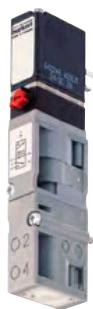
Stations on 16.5 mm grid spacing accommodate Burkert Type 6526 and Type 6527 solenoid valves. Each valve consists of a polyamide pneumatic valve body actuated by a Type 6106 rocker solenoid pilot. The tilting rocker armature moves without friction on a pivoting bearing, providing rapid actuation times without requiring baseline lubrication.
| Valve Type | Circuit Function | Orifice [mm] | Flow QNn [l/min] | Pressure Range [bar] | Opening Time [ms] | Closing Time [ms] | Nominal Power | Article No. |
|---|---|---|---|---|---|---|---|---|
| Type 6526 | 3/2-way NC (CF C) | 6.0 | 700 | 1.0–10.0 (ext. pilot) | 20 | 12 | 2 W (24 V DC) | 156842 |
| Type 6526 | 3/2-way NC (CF C) | 6.0 | 700 | 2.0–10.0 | 20 | 12 | 2 W (24 V DC) | 156318 |
| Type 6526 | 3/2-way NC (CF C) | 6.0 | 700 | 2.0–8.0 | 20 | 17 | 1 W (24 V DC) | 156840 |
| Type 6527 | 3/2-way NO (CF D) | 6.0 | 700 | 2.0–10.0 | 12 | 20 | 2 W (24 V DC) | 156320 |
| Type 6527 | 3/2-way NO (CF D) | 6.0 | 700 | 2.0–8.0 | 17 | 20 | 1 W (24 V DC) | 156841 |
| Type 6527 | 5/2-way (CF H) | 6.0 | 700 | 1.0–10.0 (ext. pilot) | 20 | 12 | 2 W (24 V DC) | 156828 |
| Type 6527 | 5/2-way (CF H) | 6.0 | 700 | 2.0–10.0 | 20 | 12 | 2 W (24 V DC) | 156337 |
| Type 6527 | 5/2-way (CF H) | 6.0 | 700 | 2.0–8.0 | 20 | 17 | 1 W (24 V DC) | 156827 |
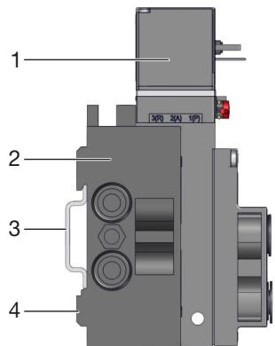
Installation of the valve unit 20053828 is performed on standard top-hat DIN rails in accordance with EN 50022 (35 x 7.5 mm or 35 x 15 mm) or directly against a flat mounting plate via M4 fixing screws.
Pneumatic Piping Precautions
Working ports 2 and 4 utilize D8 push-in connections engineered according to ISO 14743:2020. Hoses must possess a minimum hardness of 40 Shore D and adhere strictly to dimensional tolerances:
| Hose Material | Outer Diameter (OD) | Permitted OD Tolerance | Minimum Tensile Holding Force |
|---|---|---|---|
| Polyamide (PA) | 8 mm | ±0.08 mm | 170 N |
| Polyurethane (PU) | 8 mm | ±0.10 mm | 150 N |
To ensure positive claw engagement and airtight sealing, cut all pneumatic lines perpendicular to the longitudinal axis using a sharp hose cutter. Inspect tube ends for scratches, flattening, or longitudinal grooves before inserting the hose firmly past the internal O-ring seal to the internal physical stop.
Model 20053828 is executed with individual parallel wiring (collective connection technique). Each solenoid coil is driven by direct wiring from control system outputs through screw-clamp collective modules:
| Operational Malfunction | Possible Root Cause | Corrective Action |
|---|---|---|
| Valves fail to switch | Absence or insufficiency of supply voltage (< 21.6 V DC) | Check control wiring and verify nominal 24 V DC at coil terminals |
| Manual override locked in engaged position | Rotate manual override 90° counter-clockwise to zero position | |
| Operating supply pressure below 2.0 bar | Restore supply pressure in line 1 (P) to at least 2.0 bar | |
| Delayed valve actuation or exhaust blow-by | Restricted exhaust air path (silencers clogged with particulate) | Clean or replace exhaust silencers on ports 3 (R) and 5 (S) |
| System pressurized while valves were in energized state | Vent system and re-pressurize manifold block with coils de-energized | |
| External leakage between module blocks | Missing, twisted, or crushed O-ring seals between modules | Disassemble sub-blocks, inspect seating grooves, and install fresh seals |
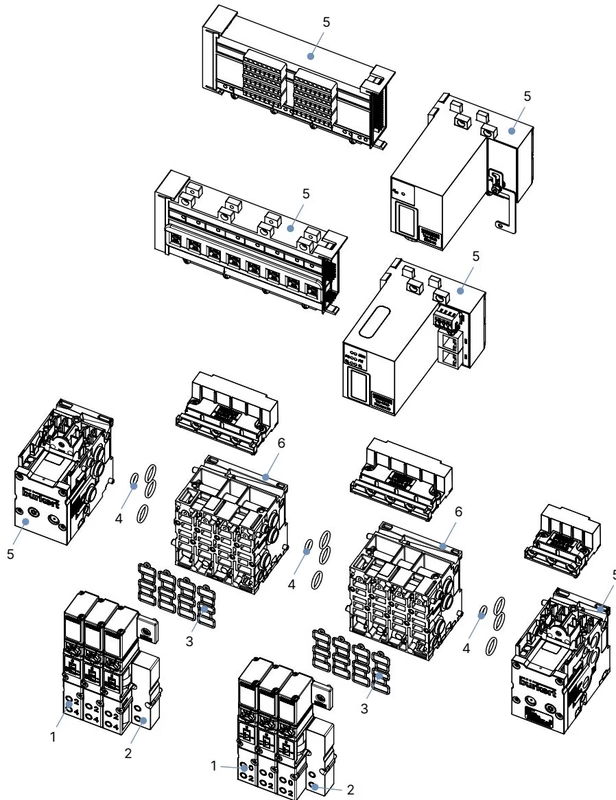
| Item Pos. | Component Description | Quantity per Pack | Article Number |
|---|---|---|---|
| 1 | Replacement valves Type 6526 / Type 6527 | 1 | Refer to valve ordering table |
| 2 | Cover plate for unused valve station Type 6526/6527 | 1 | 653765 |
| 3 | Spare valve seals FM17 (for Type 6526 / 6527) | 12 | 20016307 |
| 4 | Spare module seals for Type MP17 base blocks | 4 | 20016310 |
| 5 | Left supply unit for Type 8640, 16 mm, G 3/8 | 1 | 20042793 |
| 5 | Right supply unit for Type 8640, 16 mm, G 3/8 | 1 | 20042796 |
| 6 | Base unit for Type 8640, 16 mm, 4-fold, D8, FM17 | 1 | 20042790 |
| 6 | Base unit for Type 8640, 16 mm, 4-fold, D8, FM17, RSV (check valve) | 1 | 20042792 |
Explore similar products in our catalog


