PN16

BURKERT 20058875 (Type 8652 AirLINE) is a 16-slot valve island with stainless steel AirLINE Quick interface, Industrial Ethernet, 32 digital inputs, SIA safety shutdown, and IP20 protection.
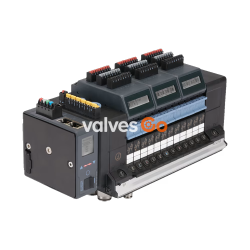
BURKERT 20058875 is a factory-configured Type 8652 AirLINE 16-slot pneumatic valve island developed for process automation environments. The unit integrates an Industrial Ethernet gateway supporting PROFINET IO, EtherNet/IP, Modbus TCP, EtherCAT, and CC-Link IE Field Basic via two RJ45 ports. It features an AirLINE Quick stainless steel baseplate adapter, enabling direct floor or wall mounting into control cabinet cutouts. Process pneumatic connections consist of stainless steel push-in fittings, with D10 mm for main supply and D6 mm for working ports. The assembly includes 32 digital inputs across four electronic modules, integrated check valves in exhaust ducts 3 (R) and 5 (S), pneumatic HotSwap in channel 1 (P), and safety-related shut-off (SIA) across valve positions 12 through 16.
Article 20058875 is delivered ready for operation with the following factory hardware configuration:
| Configuration Parameter | Specification |
|---|---|
| Valve Slot Count | 16 valve slots (16 PCE) |
| Valve Positions 1 to 11 | Type 6534: 2 × 3/2-way CF-C (normally closed, servo-assisted, with manual override) |
| Valve Positions 12 to 15 | Type 6534 SIA: 2 × 3/2-way CF-C SIA (normally closed, servo-assisted, shutdown lead) |
| Valve Position 16 | Type 6534 SIA: 5/2-way monostable CF-H SIA (servo-assisted, shutdown lead) |
| Supply Port Connection (1) | Push-in fitting D10 mm, stainless steel 1.4401 |
| Working Port Connections (2, 4) | Push-in fitting D6 mm, stainless steel 1.4401 |
| Baseplate Interface | AirLINE Quick adapter plate, stainless steel 1.4301 |
| Auxiliary Pilot Air Supply | Internal supply from main air channel |
| Additional Air Supply (Left) | Push-in connectors D6 mm and D10 mm |
| Additional Air Supply (Middle / Right) | Without additional middle or right feed |
| Intermediate Feed Modules | 1 intermediate feed quantity installed |
| Digital Input Hardware | 4 electronic modules with 8 DI each (total 32 digital inputs) |
| Exhaust Port Check Valves | Integrated check valves in ducts 3 (R) and 5 (S) |
| Valve HotSwap | Integrated pneumatic HotSwap shut-off in channel 1 (P) |
| Fieldbus Communication | Industrial Ethernet: PROFINET IO, EtherNet/IP, Modbus TCP, EtherCAT, CC-Link IE Field Basic |
| Physical Bus Ports | 2 × RJ45 female connectors (X1 and X2) |
| Parameter | Value |
|---|---|
| Body Material | Polyamide (PA) |
| Seal Materials | NBR and PUR |
| Station Width | 11 mm per valve slot |
| Maximum Expandability | Up to 24 valve slots / 48 valve functions per island |
| Manual Override | Latching, spring return (standard valves) |
| Operating Pressure Range | -1.00 bar to 10.00 bar (vacuum to 10 bar) |
| Pilot Pressure Range | 3.00 bar to 10.00 bar |
| Nominal Flow Rate QNn (Air) | 310 l/min (measured at +20 °C, 6 bar inlet pressure, 1 bar differential pressure) |
| Flow Reduction with HotSwap | Approximately 3% flow reduction |
| Operating Mode | Continuous operation (100% duty cycle) |
| Switching Time | Measured in accordance with ISO 12238 |
| Operating Voltage | 24 V DC (±10%), residual ripple 1 Vss |
| Nominal Valve Power | 0.7 W per coil (0.175 W after internal electronic power reduction) |
| Nominal Valve Current | 29 mA per coil (10 mA after power reduction) |
| Operating Medium | Lubricated or non-lubricated compressed dry air, neutral gases |
| Compressed Air Quality | ISO 8573-1:2010, Class 7.4.4 (5 µm pre-filtration recommended) |
| Ingress Protection | IP20 naked; IP65 / NEMA 4X inside closed control cabinet with AirLINE Quick stainless steel |
| Ambient & Medium Temperature | -10 °C to +55 °C |
| Storage Temperature | -20 °C to +60 °C |
| Electrical Protection Class | Class III according to DIN EN 61140, VDE 0140 |
AirLINE Quick allows Type 8652 to mount directly into the control cabinet bottom or side wall. Tubing connects from the outside directly into the stainless steel push-in couplings, eliminating bulkhead fittings and reducing enclosure dimensions.
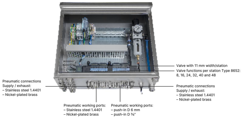
| Component / Feature | Material / Dimension |
|---|---|
| Adapter Plate Material | Stainless steel 1.4301 (or anodised aluminium) |
| Push-in Fittings Material | Stainless steel 1.4401 (or nickel-plated brass) |
| Supply / Exhaust Ports (1, 3, 5) | Push-in D10 mm (or 3/8") |
| Working Ports (2, 4) | Push-in D6 mm (or 1/4") |
| Mounting Positions | Control cabinet floor or control cabinet wall |
| Cabinet Ingress Rating | Type 4X (NEMA 250) in closed enclosures with stainless steel version |
Type 8652 supports multiple circuit functions using Type 6534 solenoid valves. The table below lists standard functions and SIA safety-related shut-off variants:
| Function Code | Valve Type | Switching Function Description |
|---|---|---|
| CF C | 3/2-way | Servo-assisted, normally closed, with manual override |
| CF C (2x) | 2 × 3/2-way | Servo-assisted, normally closed, two independent valves in 11 mm body |
| CF D (2x) | 2 × 3/2-way | Servo-assisted, normally open, two independent valves in 11 mm body |
| CF H | 5/2-way | Monostable, servo-assisted; port 1 pressurises either port 2 or port 4 |
| CF Z | 5/2-way | Bistable impulse valve with 2 coils and manual override |
| CF L | 5/3-way | Servo-assisted, middle position closed (all ports locked) |
| CF M | 5/3-way | Servo-assisted, middle position pressurised (ports 2 and 4 under pressure) |
| CF N | 5/3-way | Servo-assisted, middle position exhausted (ports 2 and 4 vented to exhaust) |
| CF C (SIA) | 3/2-way | Servo-assisted, normally closed, safety shut-off lead, without manual override |
| CF C (2x SIA) | 2 × 3/2-way | Servo-assisted, normally closed, safety shut-off lead, without manual override |
| CF H (SIA) | 5/2-way | Monostable, servo-assisted, safety shut-off lead, without manual override |
| CF L (SIA) | 5/3-way | Servo-assisted, middle position closed, safety shut-off lead, without manual override |
Dimensional layout for 16-slot, 20-slot, and 24-slot valve terminal configurations:
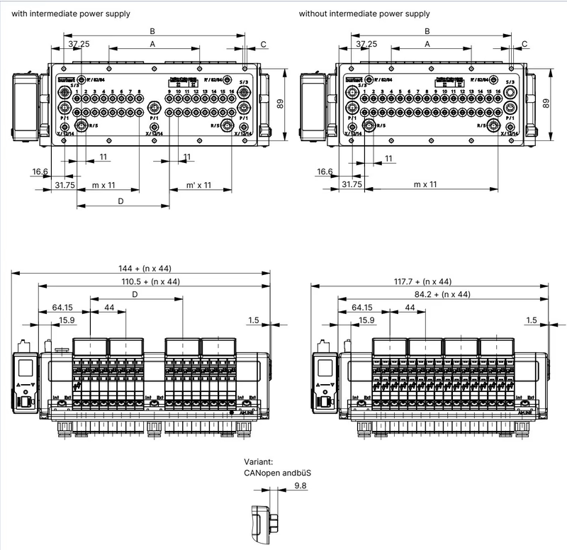
| Terminal Configuration | A [mm] | B [mm] | C [mm] | D [mm] | m | m' | n |
|---|---|---|---|---|---|---|---|
| 16-fold with intermediate supply (20058875) | 112 | 224 | 10 × M5 | 114.3 | 7 | 7 | 4 |
| 20-fold with intermediate supply | 134 | 268 | 10 × M5 | 158.3 | 11 | 7 | 5 |
| 24-fold with intermediate supply | 156 | 312 | 10 × M5 | 158.3 | 11 | 11 | 6 |
| 16-fold without intermediate supply | 99 | 198 | 10 × M5 | — | 15 | — | 4 |
| 20-fold without intermediate supply | 121 | 242 | 10 × M5 | — | 19 | — | 5 |
| 24-fold without intermediate supply | 143 | 286 | 10 × M5 | — | 23 | — | 6 |
Mounting Hardware
Fastening to the cabinet base requires screw set M5 × 10 A2 DIN 6912 (Bürkert order code 308661).
Type 8652 separates the power supply for the electronic control/display logic from the actuator valve coil supply.
A 5-pin spring-loaded terminal provides logic power and büS system communication (conductor cross section ≤ 1.5 mm²):
| Terminal Pin | Conductor Colour | Signal Assignment |
|---|---|---|
| 1 | Red | +24 V DC logic supply |
| 2 | White | CAN_H (büS communication) |
| 3 | Green | Shielding |
| 4 | Blue | CAN_L (büS communication) |
| 5 | Black | 0 V DC (GND) |
A separate 2-pin spring-loaded terminal supplies auxiliary electrical power to the solenoid valve coils:
| Terminal Pin | Conductor Colour | Signal Assignment |
|---|---|---|
| 1 | Red | AUX +24 V DC valve supply |
| 2 | Black | 0 V DC (GND) |
Independent Power Supply
To maintain galvanic isolation and safety shut-off integrity, power logic and valve coils from separate circuits. Do not bridge the 24 V logic supply with the AUX 24 V valve supply.
Dual RJ45 ports (X1, X2) provide Industrial Ethernet connectivity with integrated switch functionality:
| RJ45 Pin | Signal Assignment |
|---|---|
| Pin 1 | TX+ (Transmit Data +) |
| Pin 2 | TX- (Transmit Data -) |
| Pin 3 | RX+ (Receive Data +) |
| Pin 4 | Not connected (N.C.) |
| Pin 5 | Not connected (N.C.) |
| Pin 6 | RX- (Receive Data -) |
| Pin 7 | Not connected (N.C.) |
| Pin 8 | Not connected (N.C.) |
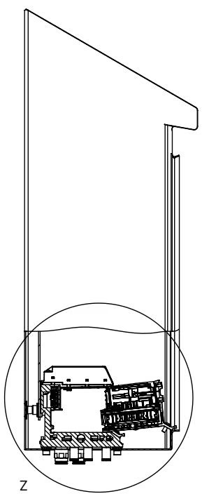
Pneumatic HotSwap allows individual Type 6534 solenoid valves to be replaced under working pressure without depressurising the island or interrupting adjacent stations. When installing Type 8652 inside a control cabinet, maintain the minimum clearance from the cabinet front door and rear mounting plate as illustrated above to allow manual valve release.
Exhaust Duct Protection
Integrated non-return check valves in exhaust channels 3 (R) and 5 (S) prevent back-pressure surges from triggering unintended actuator movements in shared exhaust manifolds.
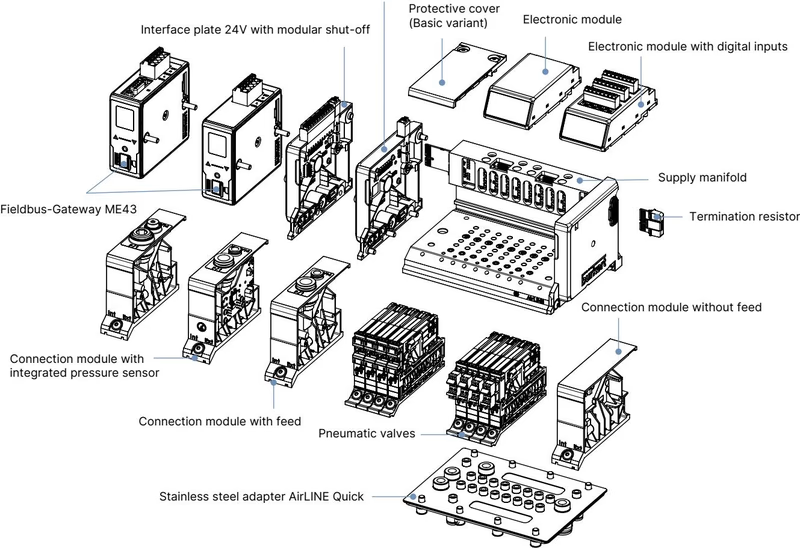
Type 8652 uses modular electronic modules for process feedback. Article 20058875 includes four 8DI electronic modules providing 32 digital inputs directly on the valve terminal.
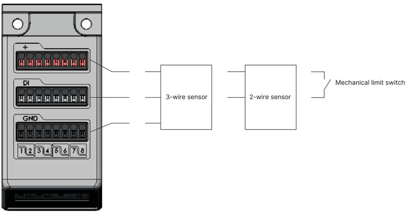
| Technical Parameter | 8DI Module Specification |
|---|---|
| Compatible Sensors | 2-wire proximity sensors, 3-wire PNP sensors, mechanical limit switches |
| Switching Thresholds | V_OFF = 0 V to 5 V; V_ON = 10 V to 30 V |
| Sensor Supply Voltage | 24 V DC (supplied from electronic module) |
| Sensor Current Limit | Max. 30 mA per sensor channel |
| Input Current at V_ON | Max. 5.7 mA per channel (typical at 24 V DC) |
| Input Impedance | > 4 kΩ |
| Cable Limitations | Maximum cable length < 30 m; cross section ≤ 1.5 mm² |
| Galvanic Isolation | No; all input channels share a common reference potential |
Depending on the connected sensor technology, the electronic module generates channel diagnostics:
| Diagnostic Status | 3-Wire Sensor | 2-Wire Sensor | Mechanical Limit Switch |
|---|---|---|---|
| Sensor Actuated | Supported | Supported | Supported |
| Sensor Not Actuated | Supported | Supported | Supported |
| Short Circuit Detection | Supported | Not supported | Not supported |
| Wire Break Detection | Not supported | Supported | Not supported |
Article 20058875 integrates Type 6534 SIA valves at positions 12 through 16. Each SIA valve has an external two-core flying lead with a dedicated, coded pluggable terminal. Opening this loop directly interrupts the coil power circuit, causing the valve to return to its de-energised safe position regardless of fieldbus commands.
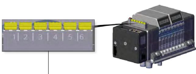
| Parameter | Value |
|---|---|
| SIA Terminal Type | Pluggable coded screw/spring terminal, 2-pin per valve |
| SIA Module Terminal | Pluggable spring-loaded terminal block, 12-pin (AWG 26–16, 0.14–1.5 mm²) |
| External Contact Type | Potential-free contact (mechanical emergency stop switch, safety relay) |
| Contact Switching Capacity (Individual Valve) | 0.5 A / 24 V DC |
| Contact Switching Capacity (Module Terminal) | 1.5 A / 24 V DC |
| Factory Delivery State | Bridged with factory jumper clips; remove jumper before connecting field wiring |
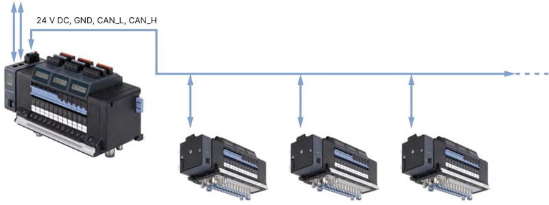
The integrated Industrial Ethernet module operates as a fieldbus master for downstream Bürkert büS valve islands. Configuration, diagnostics, and parameter setting are handled through the Bürkert Communicator Type 8920 software via the büS service interface.
Bürkert Communicator software operates on the EDIP platform. Using the USB büS interface set (order code 772426), commissioning engineers can backup and restore configurations, set cycle parameters, and monitor channel diagnostic registers in real time.
| Valve Model / Function | Circuit Function | Orifice [mm] | Flow QNn [l/min] | Pressure Range [bar] | Opening / Closing Time [ms] | Article Number (with screws) |
|---|---|---|---|---|---|---|
| Standard Type 6534 | 2 × 3/2-way CF-C | 4 | 270 | Vac to 10 | 15 / 15 | 301374 (Spare kit: 296031) |
| Standard Type 6534 | 2 × 3/2-way CF-D | 4 | 310 | Vac to 10 | 15 / 15 | 301375 (Spare kit: 296032) |
| Standard Type 6534 | 5/2-way CF-H | 4 | 290 | Vac to 10 | 20 / 25 | 301376 (Spare kit: 296033) |
| Standard Type 6534 | 5/2-way CF-Z impulse | 4 | 290 | Vac to 10 | 20 / 25 | 301377 (Spare kit: 296034) |
| Standard Type 6534 | 5/3-way CF-L closed | 4 | 275 | Vac to 10 | 15 / 15 | 301380 (Spare kit: 296036) |
| Standard Type 6534 | 5/3-way CF-M pressurised | 4 | 300 | Vac to 10 | 20 / 20 | 301379 (Spare kit: 296035) |
| Standard Type 6534 | 5/3-way CF-N exhausted | 4 | 300 | Vac to 10 | 20 / 20 | 301381 (Spare kit: 296039) |
| Dummy Valve Plate | — | — | — | — | — | 335779 (Spare kit: 327614) |
| Type 6534 SIA | 2 × 3/2-way CF-C SIA | 4 | 270 | Vac to 10 | 15 / 15 | 338802 (Spare kit: 336443) |
| Type 6534 SIA | 5/2-way CF-H SIA | 4 | 290 | Vac to 10 | 20 / 25 | 338805 (Spare kit: 336444) |
| Type 6534 SIA | 5/3-way CF-L SIA | 4 | 275 | Vac to 10 | 15 / 15 | 346830 (Spare kit: 336523) |
| Description | Order Code |
|---|---|
| Fieldbus Gateway Type ME43 Industrial Ethernet (PROFINET, EtherNet/IP, Modbus TCP, EtherCAT) | 301799 |
| Fieldbus Gateway Type ME43 PROFIBUS DP | 301803 |
| Fieldbus Gateway Type ME43 büS / CANopen | 301802 |
| Fieldbus Gateway Type ME43 PROFINET S2 | 20081296 |
| 5-pin spring-loaded terminal plug (communication and logic power) | 920180 |
| 2-pin spring-loaded terminal plug (auxiliary valve coil power) | 920442 |
| USB büS interface set 1 (Type 8923) for Bürkert Communicator | 772426 |
| AirLINE Quick M5 × 10 A2 DIN 6912 fastening screws (set of 10) | 308661 |
| Height adapter 16-fold with intermediate supply | 754962 |
| Retaining plate 16-fold with intermediate supply (cabinet exterior) | 60005568 |
When ordered with ATEX/IECEx (code PX68) or North American HazLoc (code PU17) certification, Type 8652 is rated for use in Zone 2/22 and Class I, Division 2 environments:
Explosive Atmosphere Safety Restrictions
Explore similar products in our catalog