Transit-Time Ultrasonic

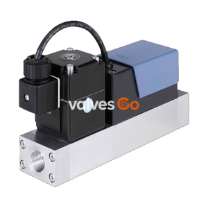
BURKERT 20064744 (Type 8745) Mass Flow Controller for N2 nitrogen. Features 500 SLPM nominal flow rate, 24 V DC supply, G 1/4" internal thread, and 4-20 mA analogue interface.
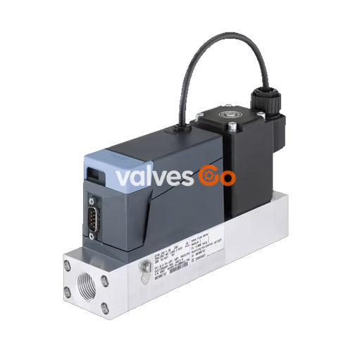
The BURKERT 20064744 (Type 8745) is a high-performance Mass Flow Controller (MFC) designed for controlling the mass flow of large gas quantities. This specific configuration is optimized for N2 nitrogen with a nominal flow rate of 500 SLPM. It features a 24 V DC supply, G 1/4" internal thread, and a 4-20 mA analogue interface. The thermal inline sensor located directly in the main gas stream achieves very fast response times with minimal pressure loss. As the actuator, a Bürkert direct-acting proportional valve guarantees high response sensitivity.
| Property | Description |
|---|---|
| Seal Material | FKM (Fluor rubber) |
| Housing Material | PC (polycarbonate) |
| Base Block Material | Aluminium |
| Wetted Parts (Sensor) | Stainless steel 1.4404/316L, Al₂O₃, PPS GF40, epoxy resin, silicon, silicon nitride |
| Operating Voltage | 24 V DC (±10% voltage tolerance, ±2% residual ripple) |
| Analogue Interface | 4...20 mA (Input impedance: <300 Ω, Maximum load: 400 Ω) |
| Operating Medium | N2 nitrogen (Calibration medium: Air) |
| Medium Temperature | -10 °C to +70 °C |
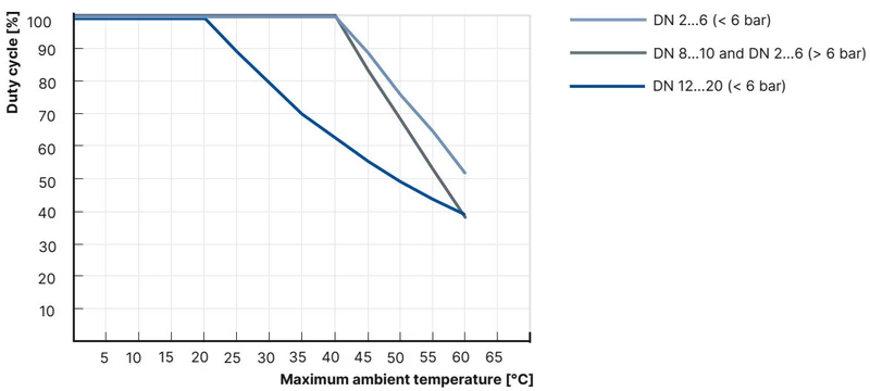
| Ambient Temperature | -10 °C to +50 °C |
| Degree of Protection | IP20 |
| Installation Position | Horizontal or vertical |
Small nominal flow rates, with internal thread
| Thread (A) | Thread depth [mm] |
|---|---|
| G 1/4 | 12 |
| NPT 1/4 | 11 |
| G 3/8 | 12 |
| NPT 3/8 | 11 |
| G 1/2 | 15 |
| NPT 1/2 | 14 |
| G 3/4 | 16 |
| NPT 3/4 | 15 |
D-Sub plug, 9-pin
| Pin | Assignment |
|---|---|
| 1 | Digital input |
| 2 | GND (for supply voltage and digital input) |
| 3 | 24 V |
| 4 | Relay, normally closed contact |
| 5 | Relay, reference contact |
| 6 | Set-point value input + |
| 7 | Set-point value input GND |
| 8 | Actual value output |
| 9 | Actual value output GND |
| Housing | Shielding |
Terminal strip, 6-pin
| Pin | Assignment |
|---|---|
| 1 | 24 V |
| 2 | GND |
| 3 | Set-point value input + |
| 4 | Set-point value input GND |
| 5 | Actual value output + |
| 6 | Actual value output GND |
INFO
All values refer to 1013.25 mbar abs and 273.15 K (0 °C) (Index N).
| Gas | Min. Q_N [l/min] | Max. Q_N [l/min] |
|---|---|---|
| Acetylene | 20 | 320 (from 65 l/min with air calibration) |
| Ammonia | 8 | 1000 |
| Argon | 20 | 1600 |
| Carbon dioxide | 20 | 800 |
| Air | 20 | 2500 |
| Methane | 20 | 1200 |
| Propane | 20 | 200 |
| Oxygen | 20 | 2500 |
| Nitrogen | 20 | 2500 |
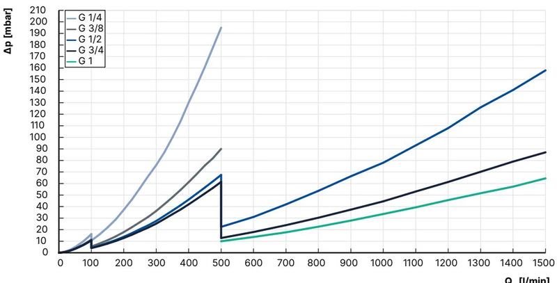
The diagram shows an example of the pressure loss curves with air flowing through. To determine the pressure loss of other gases, the corresponding air equivalent must first be calculated and the base block used for the other gas must be taken into account.
Formula for calculating the pressure loss in an MFM: $\Delta P_{Gas} = \Delta P_{Air} \sqrt{\frac{\rho_{NGas}}{\rho_{NAir}}}$
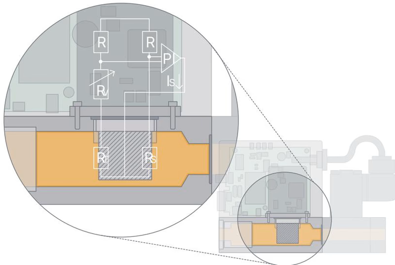
This sensor works as a hot-film anemometer in the so-called CTA operational mode (Constant Temperature Anemometer). Two resistors with a precisely specified temperature coefficient located directly in the media flow and three further resistors are connected to form a measuring bridge. The first resistor in the gas flow measures the fluid temperature, while the second, low-value resistor is always heated just enough to keep it at a fixed, specified excess temperature with respect to the fluid temperature. The heating current required for this is a measure of the heat dissipation and represents the primary measured variable.
Adequate flow conditioning within the MFC and calibration with high-quality flow standards ensure that the amount of gas flowing through per time unit can be derived from the primary signal with a high degree of accuracy.
Safety Information
Electrostatically sensitive components: The device contains electronic components that are susceptible to the effects of electrostatic discharging (ESD). Do not touch electronic components when the supply voltage is connected. Electric shock: Touching live parts can result in severe electric shock. Before working on the device or system, switch off the power supply. Medium under pressure: Medium under pressure can seriously injure people. Before working on the device or system, switch off the pressure and vent or empty the lines.
Explore similar products in our catalog