


PN25

BURKERT 20064930 (Type 2100) is a pneumatically operated 2/2-way angle seat valve with DN65 SMS 3008 weld ends, normally closed function, PTFE seat seal, and PN25 pressure rating.
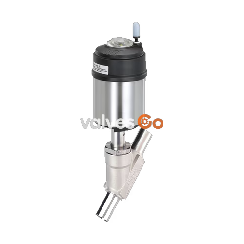
BURKERT 20064930 (Type 2100) is a pneumatically operated 2/2-way angle seat valve designed for decentralized process automation in hygienic, utility, and demanding industrial fluid applications. Configured with an SMS 3008 pipe weld end connection in nominal size DN65 (pipe outer diameter 63.5 mm, wall thickness 1.6 mm), this valve operates under Control Function A (normally closed by spring force). The process fluid enters below the valve seat, allowing safe shut-off of liquids, steam, and gases without water hammer risk.

The ELEMENT design platform integrates an internal pilot air routing system inside the stainless steel actuator, eliminating external tubing when paired with modular control heads. Spindle sealing relies on a self-adjusting PTFE V-ring packing gland with spring compensation, tested to Leakage Rate A according to DIN EN 12266-1. The valve provides full CIP and SIP capability, with wetted materials compliant with EC Regulation 1935/2004.
| Specification Parameter | Value |
|---|---|
| Article Number | 20064930 |
| Valve Type | 2100 ELEMENT |
| Construction | 2/2-way angle seat valve, complete assembly |
| Nominal Diameter (Seat & Orifice) | DN 65 (2 1/2") |
| Port Connection Type | Weld end SMS 3008 (OD 63.5 mm, ID 60.3 mm, Wall 1.6 mm) |
| Face-to-Face Installation Length | 230 mm |
| Flow Direction | Below the seat (flow to open) |
| Control Function | A: Normally closed by spring force (NC) |
| Flow Coefficient Kv (Water, 20 °C, Δp 1 bar) | 85 m³/h |
| Maximum Operating Pressure | 16 bar (15 bar for compressible fluids group 1 per PED 2014/68/EU) |
| Nominal Pressure Class | PN 25 (DIN EN 1333) / Class 150 (DIN EN 1759) |
| Minimum Pilot Pressure | 5.6 bar |
| Maximum Pilot Pressure | 7.0 bar |
| Medium Temperature Range | -10 °C to +185 °C |
| Ambient Temperature Range | -10 °C to +100 °C (threaded air port) / -10 °C to +60 °C (push-in connector) |
| Pilot Air Ports | Push-in connector Ø 6 mm (1/4") or G 1/8 thread |
| Seat Leakage Class | Rate A according to DIN EN 12266-1 (test medium: air) |
| Degree of Protection | IP65 / IP67, NEMA Type 4X |
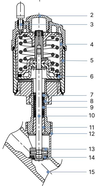
| Item No. | Component | Material |
|---|---|---|
| 1 | Ground terminal | Stainless steel 1.4301 / 1.4305 (for ATEX execution) |
| 2 | Optical position indicator | Polysulfone (PSU) |
| 3 | Pilot air ports | Polypropylene (PP) standard push-in; G 1/8 stainless steel 1.4305 on request |
| 4 | Actuator cover | Polyphenylene sulphide (PPS) |
| 5 | Actuator casing | Stainless steel 1.4561 (316Ti) |
| 6 | Piston seal | Fluoroelastomer (FKM) |
| 7 | Actuator spring | Stainless steel 1.4310 |
| 8 | Pipe / body extension | Stainless steel 1.4401 (316) / 1.4404 (316L) |
| 9 | Packing gland | Filled PTFE V-rings with spring compensation |
| 10 | Spindle | Stainless steel 1.4401 (316) / 1.4404 (316L) |
| 11 | Spindle guide | Polyether ether ketone (PEEK) |
| 12 | Body seal | Graphite (PTFE optional) |
| 13 | Swivel plate | Stainless steel 1.4401 (316) / 1.4404 (316L) |
| 14 | Seat seal | PTFE (Polytetrafluoroethylene) |
| 15 | Valve body | Stainless steel CF3M (cast 316L equivalent) |
INFO
Lubricants utilized in the spindle packing gland and pneumatic actuator assembly are certified according to NSF H1 food-grade standards.
BURKERT 20064930 is fitted with actuator size 130 mm (code P) to deliver shut-off against media pressures up to 16 bar.
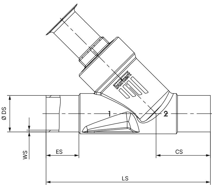
| Parameter | Dimension (mm) |
|---|---|
| Nominal Diameter DN | DN 65 (2 1/2") |
| Connection Standard | SMS 3008 |
| Pipe Outer Diameter (DS) | 63.5 mm |
| Pipe Wall Thickness (WS) | 1.6 mm |
| End-to-End Installation Length (LS) | 230 mm |
| Centerline to Weld End (ES) | 26 mm |
| Centerline to Lower Flange / Body Base (CS) | 56 mm |
| Actuator Size | Ø 130 mm (P) |
| Actuator Outer Diameter (Ø A) | 159 mm |
| Overall Height from Centerline (B / H) | 324 mm |
| Actuator Angle Clearance (K / M) | 285 mm |
| Overall Height with Type 8690 / 8697 Control Unit | 362 mm |
| Overall Height with Type 8691 / 8695 Control Head | 386 mm |
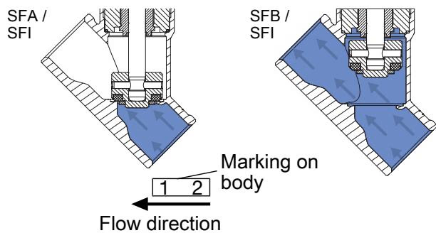
Article 20064930 operates with flow entering below the seat. In this configuration, fluid pressure acts beneath the swivel plate, assisting the opening motion when pilot pressure is supplied to pilot port 1. When pilot pressure vents, spring force acts downward to close the swivel plate against incoming media flow.
Flow Direction Recommendation
Flow direction below the seat is engineered for liquid media, steam, and gases. Closing against media flow prevents hydraulic shock (water hammer) in pipeline networks.
Water Hammer Prevention
Do not reverse fluid flow direction to above the seat when conveying liquid media. Liquid water hammer can cause rupture of pipelines and valve housings.
Operating limits are determined by the pressure-temperature rating of the body material and the standard pipe connection.
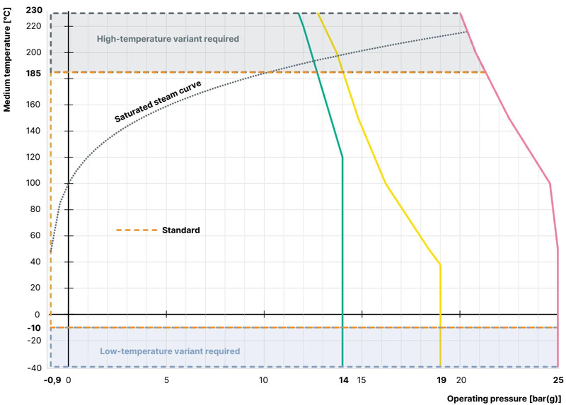
| Medium Temperature (°C) | Maximum Operating Pressure PN25 (bar) | Maximum Operating Pressure Class 150 (bar) |
|---|---|---|
| -10 °C to +50 °C | 25.0 bar | 18.4 bar |
| +100 °C | 24.5 bar | 16.2 bar |
| +150 °C | 22.4 bar | 14.8 bar |
| +185 °C | 21.0 bar | 14.0 bar |
For 20064930, the maximum operating pressure is 16 bar up to 140 °C, derating in accordance with the Class 150 curve at higher temperatures.
Prior to welding the stainless steel body into the piping system, the actuator must be separated from the body to protect the internal seals and spring mechanisms from thermal damage.
| Nominal Diameter | Actuator Size | Tightening Torque | Tolerance |
|---|---|---|---|
| DN 15 | 40 (C), 50 (D), 63 (E) | 45 Nm | +10 / -5 Nm |
| DN 20 | 40 (C), 50 (D), 63 (E), 80 (F) | 50 Nm | +10 / -5 Nm |
| DN 25 | 50 (D), 63 (E), 80 (F) | 60 Nm | +10 / -5 Nm |
| DN 32 | 63 (E), 80 (F), 100 (G) | 65 Nm | +10 / -5 Nm |
| DN 40 | 63 (E), 80 (F), 100 (G), 125 (H) | 65 Nm | +10 / -5 Nm |
| DN 50 | 70 (M), 90 (N), 130 (P) | 70 Nm | +10 / -5 Nm |
| DN 65 | 90 (N), 130 (P) | 70 Nm | +10 / -5 Nm |
| DN 80 | 125 (H), 130 (P) | 120 Nm | +10 / -5 Nm |
The pilot air connections can be rotated continuously over 360° to adjust to pneumatic tubing layouts.
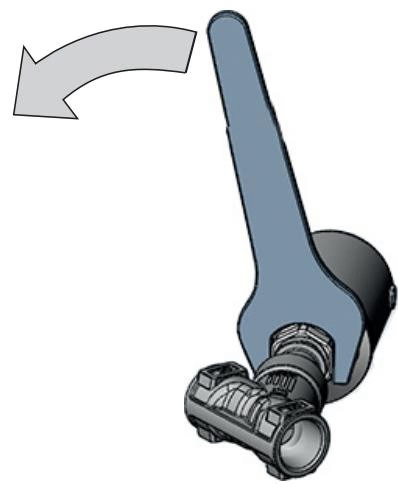
Rotation Precaution
Rotate the actuator only in the designated clockwise direction indicated on the housing. Turning in the opposite direction risks loosening the threaded body connection joint.
Pilot air supply lines connect to pilot port 1 (marked on the actuator cover). For standalone valves, the supplied exhaust silencer is installed into free port 2. In aggressive process environments, route free exhaust ports via pneumatic tubing into a neutral atmosphere.
Inspect the valve at regular maintenance intervals for external tightness and mechanical integrity.
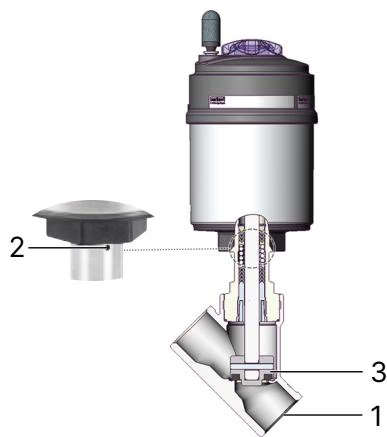
| Inspection Zone | Check Item | Corrective Action |
|---|---|---|
| Media Connectors (1) | Pipeline weld joints and body connection | Tighten body connection or reweld line connection |
| Relief Bore (2) | Spindle packing gland tightness | Replace packing gland seal kit or complete actuator |
| Valve Seat / Swivel Plate (3) | Internal seat tightness across the port | Replace the swivel plate and PTFE seat seal kit |
| Malfunction | Possible Cause | Corrective Action |
|---|---|---|
| Actuator does not actuate | Pilot air connected to wrong port | Connect control pressure to pilot air port 1 |
| Pilot air pressure below 5.6 bar | Increase pilot air pressure to between 5.6 and 7.0 bar | |
| Operating fluid pressure exceeds 16 bar | Regulate media pressure within operating limits | |
| Valve seat passes fluid when closed | Operating pressure exceeds spring force | Verify line pressure does not exceed 16 bar |
| Solid particles trapped on seat | Flush line; install upstream strainer (mandrel size 1 mm) | |
| PTFE seat seal worn or damaged | Install replacement swivel plate kit | |
| Medium escapes from relief bore | Packing gland V-rings worn | Replace packing gland set using installation tool 683223 |
Explore similar products in our catalog



