

PN16

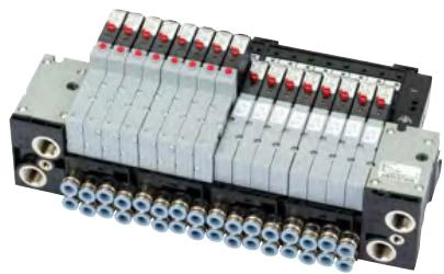
BURKERT 20066296 (Type 8640) is an 11 mm modular pneumatic valve island with mixed 3/2-way valves, Sub-D 25-pin multipole interface, G 1/4 supply ports, D6 bottom working ports, and IP20 DIN-rail mounting.
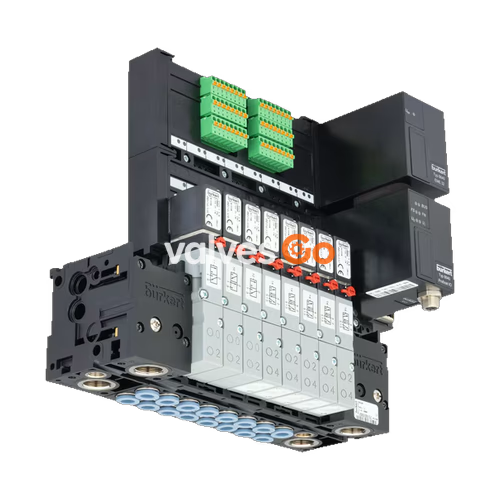
BURKERT 20066296 (Type 8640) is a modular pneumatic valve island designed for compact industrial automation, featuring an 11 mm station width per valve slot and Revision 3 (REV3) architecture. The unit integrates a mixed valve population with 3/2-way pilot valve functions, controlled via a multi-pole Sub-D 25-pin electrical connection. Pneumatic supply connections 1 (P), 3 (R), and 5 (S) are configured with G 1/4 threads, while working ports 2 (A) and 4 (B) utilize D6 push-in connectors routed through the bottom of the pneumatic module. Operating within an air pressure window of 2.50 bar to 10.00 bar, the valve island accommodates medium temperatures from 0 °C to 50 °C and ambient operating conditions up to 55 °C, mounted directly to EN 50022 DIN rails with an IP20 ingress protection rating.

| Technical Parameter | Specification Value |
|---|---|
| Product Type | Type 8640 Modular Valve Island |
| Article Number (SKU) | 20066296 |
| Generation / Hardware Revision | Revision 3 (REV3) |
| Width per Station | 11 mm |
| Valve Configuration | Mixed valve population (3/2-way functions) |
| Supply Connections 1 (P), 3 (R), 5 (S) | G 1/4 threaded ports |
| Working Ports 2 (A), 4 (B) | Push-in connector D6 (6 mm outer diameter) |
| Working Port Orientation | Bottom (pneumatic module) |
| Nominal Operating Pressure Range | 2.5 bar to 10.0 bar (overpressure to atmospheric) |
| Medium Temperature Range | 0 °C to +50 °C |
| Ambient Operating Temperature | 0 °C to +55 °C |
| Storage Temperature | -20 °C to +60 °C |
| Operating Medium | Lubricated or oil-free compressed dry air, neutral gases (ISO 8573-1:2010 Class 7.4.4; 5 µm filter recommended) |
| Electrical Interface | Multi-pole Sub-D 25-pin |
| Operating Voltage | 24 V DC (±10% tolerance, max. 1 Vss residual ripple) |
| Single Valve Power Consumption | 0.8 W per single valve (2 × 0.8 W with power reduction for double valves) |
| Total Multipole Current Rating | Max. 3 A (valve total) + max. 3 A (digital inputs) |
| Protection Class | III according to VDE 0580 |
| Ingress Protection Rating | IP20 (IP65 achievable when mounted inside closed control cabinets) |
| Installation Type | Standard rail EN 50022 (35 × 7.5 mm or 35 × 15 mm) |
| Valve Body Material | Polyamide (PA) |
| Sealing Materials | FKM, NBR, and PUR |
| Integrated Check Valves | No (in ports 3/R and 5/S) |
| Pneumatic HotSwap | No (standard manifold feed) |
| Digital Inputs | 0 PCE |
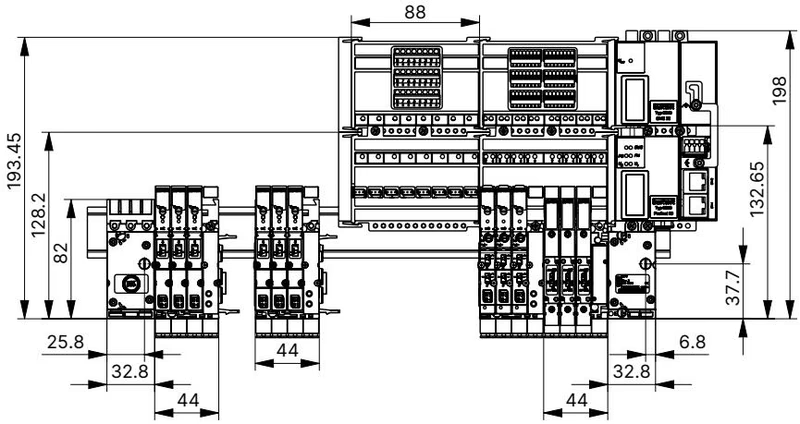
Type 8640 modular construction allows custom pneumatic and electrical interface grouping. Built-in snap connectors join basic pneumatic modules and electrical slices without requiring separate tie-rods or continuous tensioning hardware.
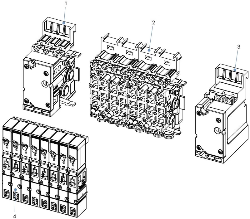
| Item | Modular Element | Component Function |
|---|---|---|
| 1 | Pneumatic connection module, left | Houses main supply and exhaust G 1/4 ports (1/P, 3/R, 5/S) |
| 2 | Basic pneumatic modules (11 mm) | Houses D6 bottom working connections (2/A, 4/B) for 2 to 24 valve slots |
| 3 | Pneumatic connection module, right | Closes the pneumatic manifold channel or provides secondary supply |
| 4 | Pilot valves (Type 6524 / Type 6525) | Mounted onto 11 mm base module stations with 2 screws |
Article 20066296 incorporates a multi-pole electrical connection module utilizing a Sub-D 25-pin connector. The multi-pin block routes control signals to individual pilot solenoids while maintaining a looped ground potential across all active stations.
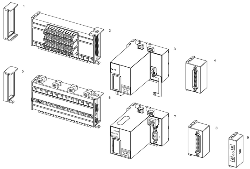
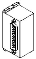
The Revision 3 (REV3) generation introduces specific mechanical updates compared to earlier REV1 and REV2 versions. These design differences affect spare valve selection and manifold sealing.
| Mechanical Feature | Type 8640 REV1 / REV2 | Type 8640 REV3 (Article 20066296) |
|---|---|---|
| Working Connection Channel Layout | Straight parallel channels | Wavy channel arrangement |
| Hose Release Ring Colour | Black | Blue |
| Pilot Valve Flange Standard | FM14 / FM15 interface | FM20 / FM24 standardized interface |
| Flow Reduction with P-Shutoff Option | Up to 50% | Up to 20% |
Revision Compatibility Notice
Pneumatic pilot valves for REV3 feature a standardized pneumatic flange pattern that differs from REV1 and REV2. Replacement valves must be matched by article number to the REV3 generation.
The 11 mm pneumatic base modules of Type 8640 accommodate Bürkert Type 6524 flipper solenoid valves and Type 6525 pilot valves. Each pilot valve features an integrated manual override as standard.
| Circuit Function | Valve Type | Pressure Range | Opening Time | Closing Time | Power | REV3 Article No. |
|---|---|---|---|---|---|---|
| CF C: 3/2-way NC | Type 6524 (DN 4.0 mm) | 2.5 ... 10 bar | 15 ms | 28 ms | 0.8 W | 20029918 |
| CF D: 3/2-way NO | Type 6524 (DN 4.0 mm) | 2.5 ... 10 bar | 15 ms | 28 ms | 0.8 W | 20029919 |
| CF H: 5/2-way | Type 6525 (DN 4.0 mm) | 2.5 ... 10 bar | 20 ms | 28 ms | 0.8 W | 20029920 |
| CF C: 2 × 3/2-way NC | Type 6524 (DN 4.0 mm) | 2.5 ... 10 bar | 12 ms | 20 ms | 2 × 0.8 W | 186260 |
All pilot valves listed achieve a nominal flow rate QNn of 300 l/min measured at +20 °C with 6 bar valve inlet pressure and 1 bar differential pressure.
Connecting pneumatic hoses into the D6 push-in connectors requires strict adherence to hose surface tolerances and preparation:
Inactive Valve Stations
If specific stations on the basic module remain unequipped with active pilot valves, seal the pneumatic ports using cover plate 661092 and install electrical connection cover 653670 to maintain pressure integrity and contact protection.
Depressurisation Requirement
Before removing hose lines, disassembling module blocks, or replacing pilot valves, completely vent all pneumatic lines and turn off the 24 V DC electrical supply.
Explore similar products in our catalog


