Up to 99.8% Efficiency

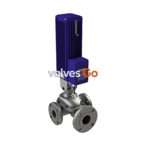
Burkert 20066855 Type 3360 electromotive 2-way angle seat control valve. Features DN 50 welded connection, PTFE seal, 24V DC supply, and up to 10 bar operating pressure.
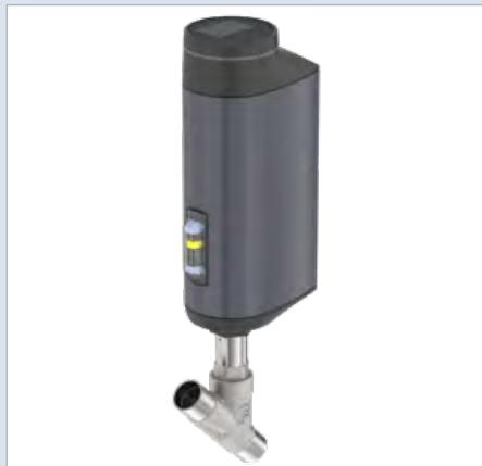
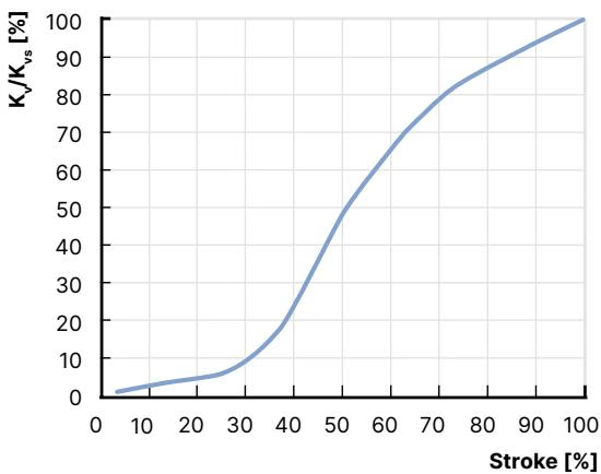
Burkert 20066855 Type 3360 electromotive 2-way angle seat control valve is the solution when it comes to control tasks under demanding operating conditions. The electromotive actuator with ball screw positions the control cone with highest precision. A unique feature is its high positioning speed up to 6 mm/s that reacts quasi delay-free to process signals and that can be varied according to customer demands. Pressure variations or shocks in the medium are not transferred to the valve position. If necessary, the safety position can be approached by an optional energy storage in case of power failure.
Actuator and valve are adapted perfectly to each other with closed design and robust surface. This ensures the hygienic requirements of a fast and residue-free cleaning. Harsh environments are no problem for the electromotive angle seat valve Type 3360 because of the degree of protection IP65 / IP67 and its high impact and vibration resistance. Unrivalled service life and tightness is guaranteed by the proven self-adjusting packing gland with exchangeable V-seals. The fieldbus-compatible Type 3360 provides many helpful functions for process monitoring, valve diagnostics and predictive maintenance.
Product Properties
Performance Data
Electrical Data
Medium Data
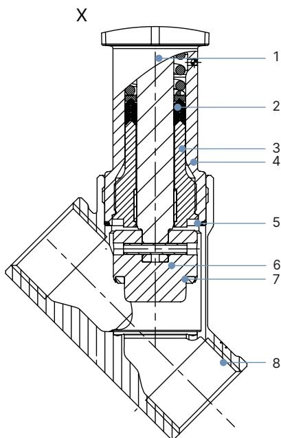
| No. | Component | Material |
|---|---|---|
| 1 | Spindle | Stainless steel 1.4401 (316)/1.4404 (316L) |
| 2 | Spindle seal | PTFE V-seals (filled) with spring compensation |
| 3 | Spindle guide | Stainless steel 1.4404 (316L) |
| 4 | Packing gland tube | Stainless steel 1.4401 (316) |
| 5 | Seal valve body | Graphite or PTFE |
| 6 | Control cone | Stainless steel 1.4571 |
| 7 | Seat seal | Stainless steel 1.4571/PTFE or PEEK seal washer |
| 8 | Valve body | Stainless steel CF3M |
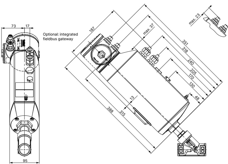
| DN | NPS | H1/B1 Standard variant | H2/B2 Fieldbus variant |
|---|---|---|---|
| 15 | 1/2 | 311 | 362 |
| 20 | 3/4 | 319 | 369 |
| 25 | 1 | 334 | 385 |
| 32 | 1 1/4 | 349 | 399 |
| 40 | 1 1/2 | 352 | 403 |
| 50 | 2 | 367 | 418 |
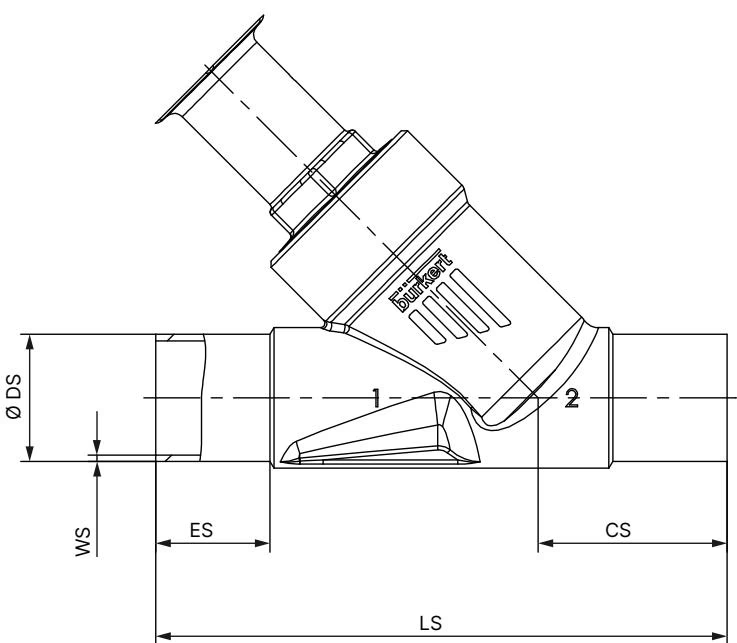
| DN | ES | CS | LS | ∅ DS | WS |
|---|---|---|---|---|---|
| 15 | 19 | 34 | 100 | 21.3 | 1.6 |
| 20 | 20 | 39 | 115 | 26.9 | 1.6 |
| 25 | 26 | 43 | 130 | 33.7 | 2 |
| 32 | 26 | 45 | 145 | 42.4 | 2 |
| 40 | 26 | 49 | 160 | 48.3 | 2 |
| 50 | 26 | 50 | 175 | 60.3 | 2 |
| 65 | 26 | 50 | 210 | 76.1 | 2.3 |
(Dimensions in mm for DIN EN ISO 1127 / ISO 4200 / DIN 11866 series B)
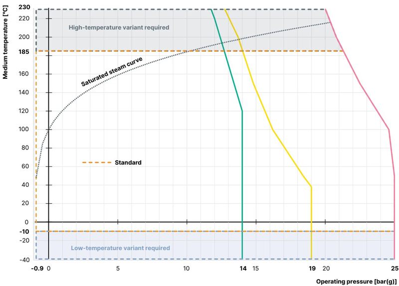
In addition to the maximum operating pressures, the application range of Bürkert process valves is limited by the nominal pressure in accordance with the relevant standard.
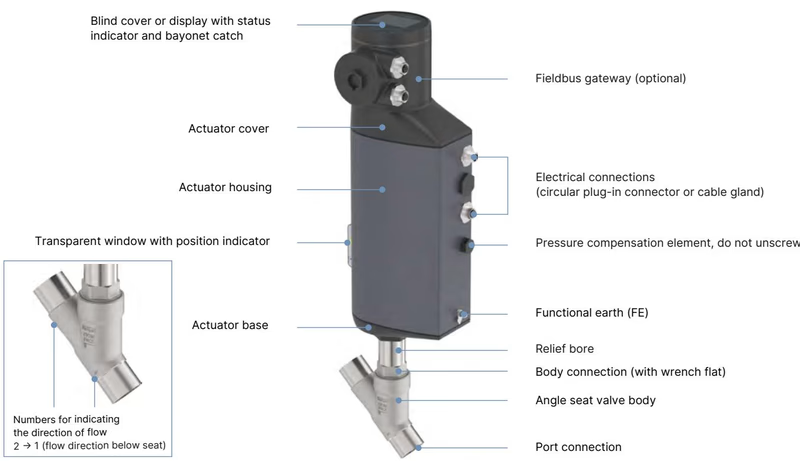
The electromotive linear drive consists of a brushless DC motor, a gear and a spindle system that transfers the force to the closing element. The integrated control electronics are controlled either by standard signals or via a fieldbus (digital). A positioner and a process controller are available as controller variants.
DANGER
Risk of injury from high pressure. Before working on the system or device, switch off the pressure and vent or drain lines.
WARNING
Risk of injury due to improper replacement of spare parts. Spare parts may be replaced only by trained technicians and with the appropriate tools.
If the supply voltage is not applied, e.g. during installation or in the event of a power failure, the valve position can be changed using the mechanical manual override.
TIP
The mechanical manual control may be used in a de-energized state only, otherwise the device may be damaged.
Explore similar products in our catalog