

PN16

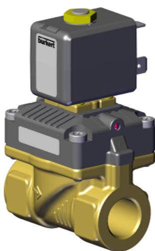
BURKERT 20069363 (Type 6211) is a 2/2-way normally closed servo-assisted solenoid valve featuring a brass body, G 1 port, 230 V AC coil, NBR seals, 0.5 to 10 bar operating pressure, and a Kv flow rate of 8.3 m3/h.
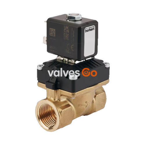
BURKERT 20069363 (Type 6211) is a servo-assisted 2/2-way solenoid valve designed to control neutral liquid and gaseous media that do not attack the brass body and NBR sealing materials. The valve operates in circuit function A as a normally closed unit, holding shut by mechanical spring force in the de-energized state. When electrical power is applied to the 230 V AC coil, the pilot armature opens first, relieving fluid pressure above the servo diaphragm and permitting the line medium to lift the main seal with a minimum operating differential pressure of 0.5 bar up to a maximum rating of 10 bar. Internal geometry provides damped operation, preventing abrupt water hammer during closure.
Configured as complete article 20069363 within the 6211 EV generation, the unit incorporates an internal G 1 process connection, a 10 mm pilot/main orifice geometry yielding an 8.3 m³/h water Kv rating, and an epoxy solenoid coil rated for 100% continuous duty. Fluid operating temperatures range from 0 °C to +70 °C, with permissible ambient operating temperatures from 0 °C to +55 °C. The valve assembly achieves an IP65 protection rating when mated with an industrial standard cable plug.
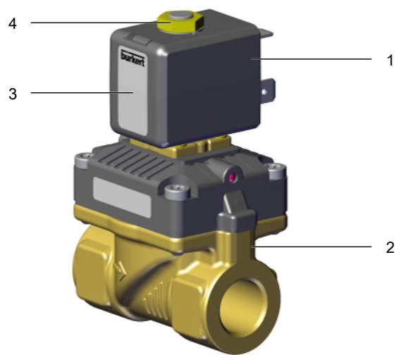
Type 6211 features a modular subassembly comprising the solenoid actuator, pressure body, and internal servo diaphragm core assembly:
| Item | Component | Function |
|---|---|---|
| 1 | Solenoid coil | Encapsulated epoxy coil class H for electromagnetic actuation |
| 2 | Valve body | Forged brass pressure-containing boundary with internal G 1 ports |
| 3 | Type label | Identification plate displaying electrical and mechanical ratings |
| 4 | Fastening nut | Hexagonal retaining nut securing the coil to the core guide tube |
In circuit function A, flow direction is strictly from port 1 (P) to port 2 (A). In the unpowered state, line pressure acts above the diaphragm via pilot equalization channels, forcing the diaphragm onto the valve seat together with the main closing spring. Upon excitation of the coil, the magnetic plunger lifts off the pilot seat. Fluid above the diaphragm vents downstream, causing pressure below the diaphragm to push it open against spring force.
| Technical Parameter | Specification Value |
|---|---|
| Valve Type | 6211 (Generation EV) |
| Article Number | 20069363 |
| Circuit Function | A (2/2-way, normally closed) |
| Number of Ports / Positions | 2 ports / 2 switching positions |
| Port Connection 1 & 2 | G 1 internal thread (parallel BSP) |
| Main Valve Orifice (P) | 10 mm |
| Flow Coefficient Kv (Water) | 8.3 m³/h (measured at +20 °C, 1 bar delta P) |
| Operating Pressure Range | 0.5 bar to 10.0 bar (differential pressure) |
| Nominal Pressure Class | PN 10 (DIN EN 1333) |
| Actuator Type | Plunger valve with servo diaphragm |
| Flow Direction | Over seat, inlet port 1 (P) to outlet port 2 (A) |
| Operating Voltage | 230 V AC (50/60 Hz), tolerance ±10% |
| Coil Power Consumption (AC08) | Inrush: 12 VA; Holding: 6.5 VA (4 W) |
| Duty Cycle | 100% continuous operation (ED 100%) |
| Medium Temperature Range | 0 °C to +70 °C (NBR seals) |
| Ambient Temperature Range | 0 °C to +55 °C |
| Maximum Fluid Viscosity | 21 mm²/s (cSt) |
| Enclosure Rating | IP65 according to EN 60529 / IEC 60529 (with plug) |
| Switching Times (DN 10 baseline) | Opening: 10 to 25 ms; Closing: 100 to 120 ms |
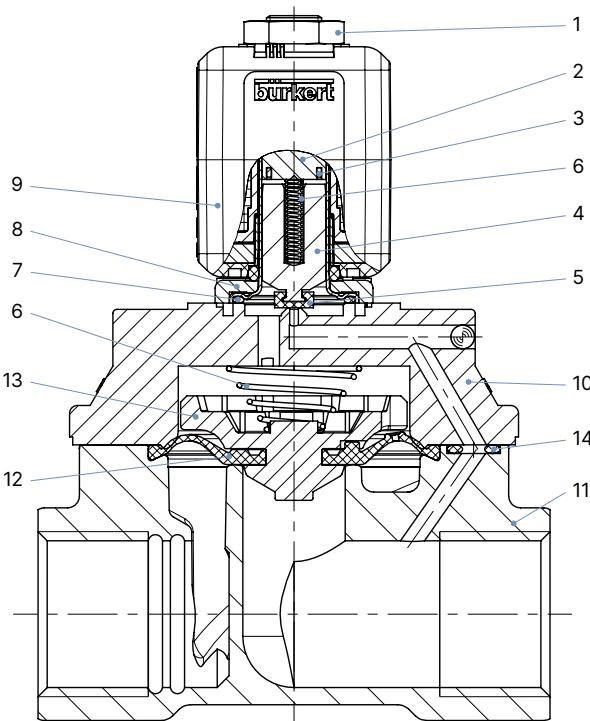
| Position | Element | Material Specification |
|---|---|---|
| 1 | Nut | Thick-film passivated steel surface (brass variant) |
| 2 | Stopper | Stainless steel 1.4113 |
| 3 | Short circuit ring | Copper (brass body variants) |
| 4 | Core | Stainless steel 1.4113 |
| 5 | Core seal | NBR (Nitrile rubber) |
| 6 | Spring | Stainless steel 1.4310 |
| 7 | O-ring | FKM |
| 8 | Flange | Thick-film passivated surface |
| 9 | Solenoid coil | Epoxy encapsulation (thermal class H) |
| 10 | Body cover | PPE/PA (polyphenylene ether / polyamide blend) |
| 11 | Valve body | Brass |
| 12 | Diaphragm | NBR (Nitrile rubber) |
| 13 | Diaphragm holder | PPS in combination with brass parts |
| 14 | O-ring | NBR (Nitrile rubber) |
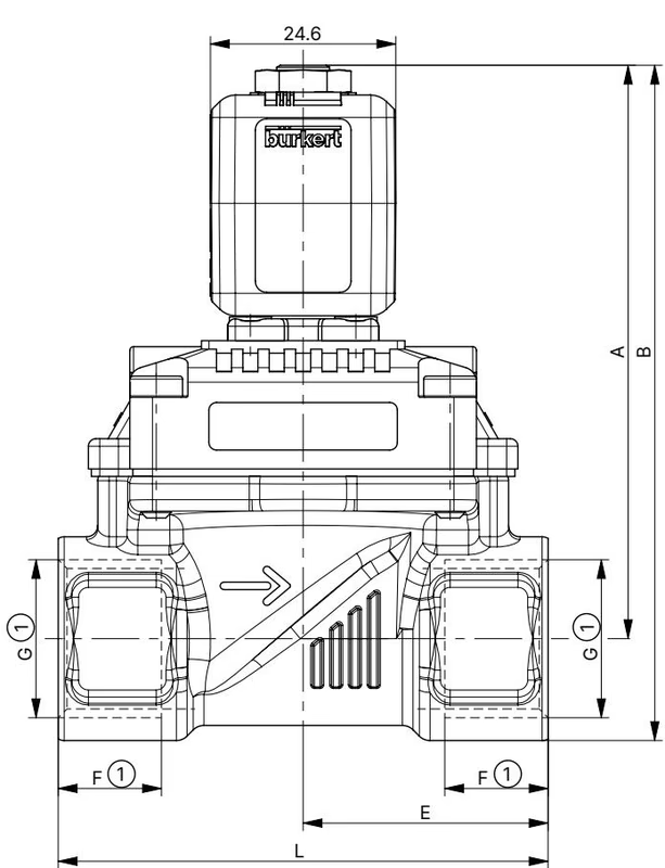
| DN | Connection Thread | A | B | C | D | E | F1 | G1 | L | SW |
|---|---|---|---|---|---|---|---|---|---|---|
| 10 | G 1/4 | 71.5 | 82.5 | 32 | 32 | 22.0 | 12.0 | G 1/4 | 50 | 22 |
| 10 | G 3/8 | 71.5 | 82.5 | 32 | 32 | 22.0 | 12.0 | G 3/8 | 50 | 22 |
| 10 | G 1/2 | 73.5 | 87.0 | 32 | 32 | 24.5 | 14.0 | G 1/2 | 50 | 27 |
| 13 | G 1/2 | 76.0 | 89.5 | 42 | 46 | 32.5 | 14.0 | G 1/2 | 65 | 27 |
| 13 | G 3/4 | 78.0 | 94.0 | 42 | 46 | 32.5 | 16.0 | G 3/4 | 65 | 32 |
| 20 | G 3/4 | 85.0 | 105.5 | 60 | 60 | 50.0 | 16.0 | G 3/4 | 100 | 41 |
| 20 / G 1 | G 1 | 85.0 | 105.5 | 60 | 60 | 50.0 | 18.0 | G 1 | 100 | 41 |
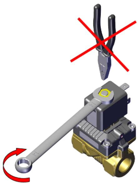
Mechanical Loading
Do not use the solenoid coil as a lever arm when tightening the valve into the pipework. Applying rotational force to the coil will distort internal guide components and fracture the body cover.
Electrical and Thermal Hazard
Never energize the solenoid coil unless it is fully assembled onto the core guide tube of an installed valve body. Operating an AC coil unmounted will lead to rapid inductive overheating, resulting in insulation failure and destruction of the coil.
Pressurized Medium Leakage
Do not attempt to tighten or loosen firmly seated coil retaining nuts while line pressure is active. Distorting the armature guide tube under internal pressure can induce sudden leakage of pressurized medium.
Type 6211 connects to external electrical control via Type 2507 Form B (industry standard) or Type 2516 Form C (DIN EN 175301-803) cable connectors:
Continuous Operation and Extended Standstill
High cycling frequency combined with maximum operating pressure accelerates normal diaphragm wear. If the system experiences prolonged downtime, actuate the valve electrically 1 to 2 times daily to prevent sedimentation build-up and armature sticking.
| Fault Condition | Potential Root Cause | Corrective Action |
|---|---|---|
| Solenoid does not pull in | Coil interrupted or short-circuited | Check coil resistance; replace coil set |
| Plunger or guide tube contaminated | Disassemble stopper, clean armature cavity | |
| Operating pressure out of bounds | Verify inlet pressure is within 0.5 to 10 bar | |
| Valve fails to close | Valve interior contaminated | Disassemble body, flush out particles |
| Pilot control orifice in diaphragm clogged | Clean servo diaphragm orifice or install wearing kit |
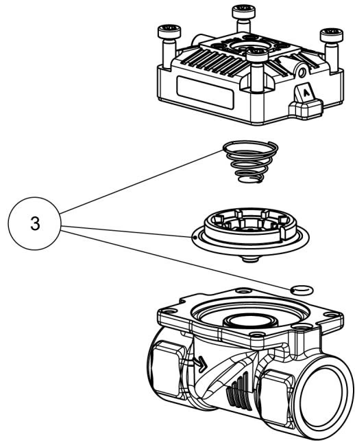
Original replacement parts from Bürkert are grouped into standardized sets:
Spare Part Ordering
When placing an enquiry or order for spare parts, always quote the specific spare part set number alongside the 8-digit identification number 20069363 found on the device type label.
Explore similar products in our catalog


