Up to 99.8% Efficiency

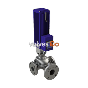
BURKERT 20071030 Type 3361 is a 24 V DC electromotive globe control valve with G 3/4 threaded ports, DN20 seat, 7.1 m³/h Kvs, AG2 1300 N actuator, Modbus TCP and büS, and SAFEPOS energy pack.
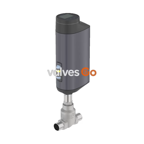
BURKERT 20071030 Type 3361 is an electromotive two-way globe control valve engineered for continuous process automation under demanding operating conditions. Driven by a brushless DC motor coupled to a precision ball screw, the valve positions its parabolic control cone at a linear travel speed of 6 mm/s with a positioning dead band of ±0.1%. Process pressure surges and line fluctuations do not displace the stem position during operation or in de-energized holding states.
Configured under article number 20071030, this unit features a cast stainless steel CF3M valve body with G 3/4 internal thread connections, a 20 mm seat diameter (DN 20), an equal percentage flow characteristic with a theoretical rangeability of 50:1, and a rated water flow coefficient Kvs of 7.1 m³/h. Fluid enters below the seat (flow direction 2 to 1). Bubble-tight shut-off meeting Class VI according to DIN EN 60534-4 is achieved via a replaceable PTFE soft seal disc. The assembly is equipped with an integrated Modbus TCP fieldbus gateway, büS system interface, an on-board graphic display with control pushbuttons, and a factory-fitted SAFEPOS energy-pack emergency storage module configured for normally open fail-safe positioning.
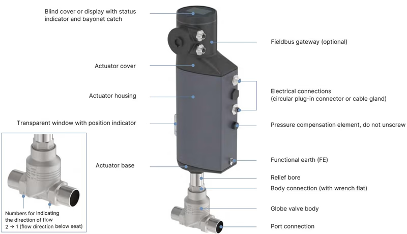
Article 20071030 utilizes the AG2 actuator frame with 1,300 N nominal thrust, delivering complete full-stroke closure in 3.3 s (adjustable up to 6.6 s depending on configuration). Operating on a 24 V DC power supply, the unit maintains 100% duty cycle rating with a standby power draw of only 2 to 5 W.
| Parameter | Specification | Standard / Condition |
|---|---|---|
| Port Size / Process Connection | G 3/4 internal thread | DIN ISO 228-1 |
| Nominal Diameter (Seat Size) | DN 20 (orifice 20 mm) | Fluidic seat size 20 |
| Flow Coefficient Kvs | 7.1 m³/h (Cv 8.3 gpm) | Water at +20 °C, DIN EN 60534-2-4 |
| Flow Characteristic | Equal percentage 50:1 | DIN EN 60534-2-4 |
| Operating Pressure Range | 0 to 25 bar(g) | Flow below seat (2 -> 1) |
| Nominal Pressure Rating | PN 25 / Class 150 | DIN EN 1333 / DIN EN 1759 |
| Seat Leakage Class | Class VI | Soft seal (PTFE), DIN EN 60534-4 |
| Operating Voltage | 24 V DC ±10% | Max residual ripple 10% |
| Maximum Current Consumption | 3.0 A | Max motor load + 1.0 A SAFEPOS charging |
| Travel Speed | 6 mm/s | 1,300 N actuator force |
| Stroke Positioning Dead Band | ±0.1% | Linear displacement sensor |
| Closing Time | 3.3 s to 6.6 s (3,300 ms typical) | Dependent on stroke and speed profile |
| Duty Cycle | 100% continuous | DIN EN 61140 Class III protection |
| Enclosure Rating | IP65 / IP67, NEMA 4X | DIN EN 60529 with mated connectors |
Wetted valve components are manufactured from austenitic stainless steels, fluoropolymers, and technical elastomers certified to European Regulation (EC) 1935/2004 for food contact compatibility. The valve stem is sealed by a self-adjusting PTFE V-ring chevron packing gland loaded with spring compensation.
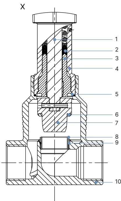
| Item | Component | Material |
|---|---|---|
| 1 | Display Housing / Blind Cover / Gateway Housing | PPS (Polyphenylene sulphide) |
| 2 | Actuator Cover | PPS |
| 3 | Static Housing Seals / O-rings | EPDM |
| 4 | Actuator Outer Housing | Aluminium, powder-coated |
| 7 | Actuator Base | PPS |
| -- | Valve Spindle (Stem) | Stainless steel 1.4401 (316) / 1.4404 (316L) |
| -- | Spindle Packing Gland Seal | PTFE V-seals (filled) with spring compensation |
| -- | Spindle Guide Bushing | Stainless steel 1.4404 (316L) |
| -- | Packing Gland Tube | Stainless steel 1.4401 (316) |
| -- | Body Connection Seal | Graphite / PTFE gasket ring |
| -- | Seat Seal Disc | PTFE soft seal washer |
| -- | Parabolic Control Cone | Stainless steel 1.4571 (316Ti) |
| -- | Screwed-in Valve Seat | Stainless steel 1.4571 (316Ti) |
| -- | Seat O-Ring | EPDM / PTFE |
| -- | Valve Body | Cast stainless steel CF3M |
Article 20071030 combines the AG2 actuator chassis with the DN 20 threaded valve body. Total height H2 with the fieldbus gateway module installed is 495 mm measured from the pipe center axis. In the closed position without active tight-closing force, the actuator head sits approximately 2 mm lower.
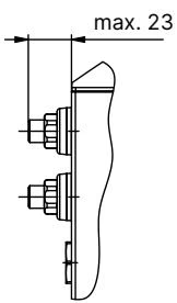
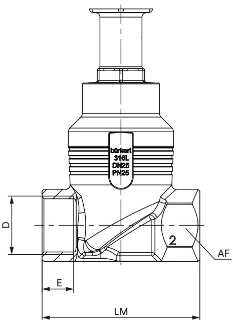
| Dimension Designation | Value (mm) | Description |
|---|---|---|
| DN (NPS) | DN 20 (3/4") | Nominal pipeline connection size |
| H1 | 423 mm | Actuator center height without fieldbus gateway |
| H2 | 495 mm | Actuator center height with integrated fieldbus gateway |
| LM | 75 mm | Face-to-face body length between port ends |
| D | G 3/4 | Thread standard according to DIN ISO 228-1 |
| E | 16 mm | Usable thread depth of ports |
| AF | 34 mm | Width across flats of body pipe connection hexagonal boss |
The screwed-in valve seat allows field reconfiguration to alternate orifice sizes if process flow demands change. For seat size 20, the profile produces an equal percentage progression over a 50:1 control ratio.
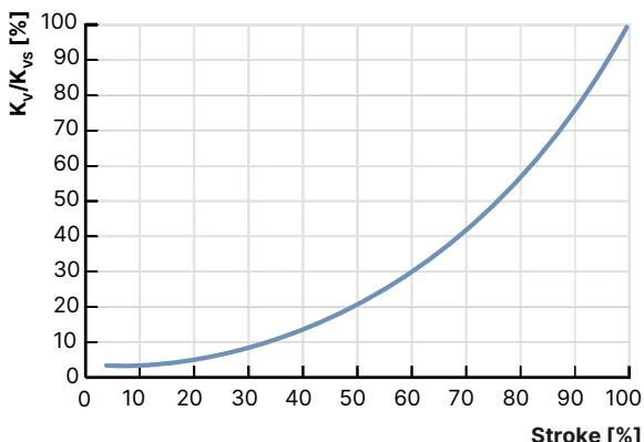
| Stroke Travel (%) | Kv Flow Value (m³/h) | Operating Pressure Limit | Leakage Class (DIN EN 60534-4) |
|---|---|---|---|
| 5% | 0.20 | 25 bar(g) | Class VI (PTFE seal) |
| 10% | 0.25 | 25 bar(g) | Class VI (PTFE seal) |
| 20% | 0.30 | 25 bar(g) | Class VI (PTFE seal) |
| 30% | 0.45 | 25 bar(g) | Class VI (PTFE seal) |
| 40% | 0.70 | 25 bar(g) | Class VI (PTFE seal) |
| 50% | 1.10 | 25 bar(g) | Class VI (PTFE seal) |
| 60% | 1.60 | 25 bar(g) | Class VI (PTFE seal) |
| 70% | 2.40 | 25 bar(g) | Class VI (PTFE seal) |
| 80% | 3.50 | 25 bar(g) | Class VI (PTFE seal) |
| 90% | 5.20 | 25 bar(g) | Class VI (PTFE seal) |
| 100% (Kvs) | 7.10 | 25 bar(g) | Class VI (PTFE seal) |
Article 20071030 is equipped with industrial M12 circular connectors located on the side and lower skirt of the actuator body. The integrated gateway features dual M12 D-coded ports for daisy-chain Ethernet line topologies.
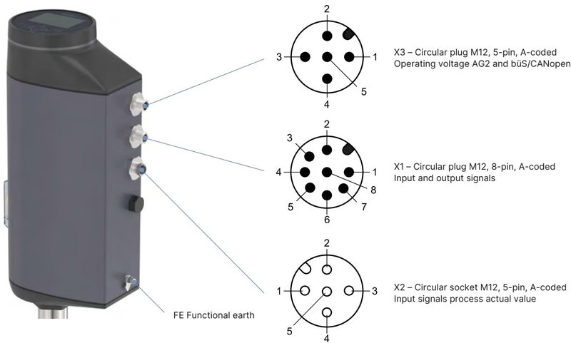
| Connector Designation | Type and Coding | Functional Circuit |
|---|---|---|
| X1 | M12 male plug, 8-pin, A-coded | Analogue setpoint input and digital I/O signals |
| X3 | M12 male plug, 5-pin, A-coded | 24 V DC power supply and büS / CANopen connection |
| X7 (Port 1 & 2) | M12 female socket, 4-pin, D-coded | Modbus TCP / Industrial Ethernet 2-port switch |
| Connector | Pin | Signal Assignment | Electrical Characteristics |
|---|---|---|---|
| X1 (8-pin M12) | 1 | Digital Input + | 0 to 5 V = log "0", 10 to 30 V = log "1" |
| 2 | GND (Digital I/O Ground) | Galvanic ground reference | |
| 3 | Digital Output 2 + | PNP transistor output, max 100 mA | |
| 4 | Digital Output 1 + | PNP transistor output, max 100 mA | |
| 5 | Analogue Output - | Isolated return path | |
| 6 | Analogue Output + | 0/4 to 20 mA (load 0-800 Ω) or 0 to 5/10 V (max 10 mA) | |
| 7 | Analogue Setpoint Input - | Isolated negative differential input | |
| 8 | Analogue Setpoint Input + | 0/4 to 20 mA (70 Ω load) or 0 to 5/10 V (22 kΩ load) | |
| X3 (5-pin M12) | 1 | CAN Shield | Cable braid screen connection |
| 2 | Supply Voltage 24 V DC | 24 V DC ±10% operating power | |
| 3 | GND / CAN_GND | Power supply negative return | |
| 4 | CAN_H | High-speed bus line | |
| 5 | CAN_L | Low-speed bus line | |
| X7 (4-pin M12) | 1 | Transmit + (TX+) | Industrial Ethernet pair 1 |
| 2 | Receive + (RX+) | Industrial Ethernet pair 2 | |
| 3 | Transmit - (TX-) | Industrial Ethernet pair 1 | |
| 4 | Receive - (RX-) | Industrial Ethernet pair 2 |
Permissible fluid pressure is bounded by the DIN EN 12516-1 PN25 pressure-temperature rating curve. For soft-seated PTFE trim, the recommended continuous fluid temperature span is -10 °C to +130 °C. The simultaneous interaction between medium temperature and external ambient temperature must be verified against derating Curve 3 for AG2 actuators fitted with an energy pack and fieldbus gateway.
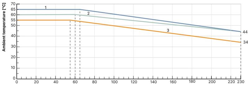
Ambient Temperature Derating
When medium temperature reaches +130 °C under maximum continuous motor loads, maximum allowable ambient temperature derates to +55 °C for units equipped with the SAFEPOS energy-pack and fieldbus module.
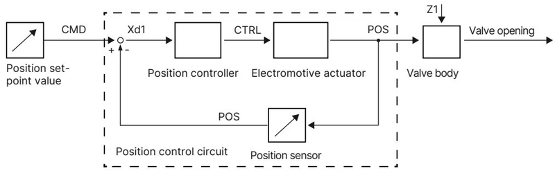
The internal microprocessor positioner compares external setpoint values (transmitted via Modbus TCP, büS, or analogue standard signal) against the real-time position from the contactless displacement sensor. Any control deviation Xd1 immediately drives the DC motor to eliminate position error.
Article 20071030 includes an internal SAFEPOS supercapacitor energy pack that triggers automatic fail-safe motion when line voltage drops below operating threshold. The delivery status is configured to drive to the fully open position (Normally Open / NO), but any intermediate stroke percentage or fully closed position can be stored in memory. The energy pack is fully charged and ready for operation within 120 s from system power-up. An internal health monitor logs capacitor aging and issues a diagnostic warning when service life approaches conclusion.
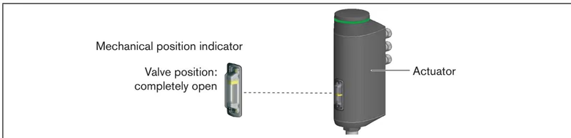
The unit incorporates a high-contrast graphic display module with tactile navigation buttons under a transparent lens. Status information, diagnostic messages, and stroke position are highlighted by a multi-color 360° LED illuminated ring. Valve position is continuously visible through an external viewing window linked directly to the spindle mechanism.
Manual manipulation is supported through two complementary modes:
Operating Precautions for Mechanical Manual Override
Only engage the mechanical manual override when power is disconnected. Coupling the tool while power is energized will cause gear drive damage. Never exceed 2 Nm torque upon reaching end-stop positions.
Whenever the actuator is uncoupled from the body, the valve seat is serviced, or replacement internal trim is mounted, the automated stroke adaptation routine X.TUNE must be executed to recalibrate mechanical travel limits and zero-point seating.
Never Run X.TUNE Under Process Pressure
Executing X.TUNE while the pipeline is pressurized causes false physical travel baselines, incorrect zero detection, and uncontrolled loop oscillations. Depressurize and drain the pipeline completely before initiating calibration.
Configuration -> Position Controller -> Maintenance -> Calibration -> X.TUNE.| Threaded Interface | Tool Requirement | Specified Tightening Torque |
|---|---|---|
| Body Connection Nut (DN 20) | Open-end wrench | 50 ± 3 Nm |
| Screwed Valve Seat (Seat size 20) | Specialized socket insert (652605) | 28 + 3 Nm |
| Spindle Guide Bushing (DN 20) | Modified socket SW21 (683222) | 25 Nm |
| Actuator Housing Cover Bolts | T25 Torx key | 5.0 Nm (crosswise) |
| Fieldbus Gateway Retaining Screw | 3 mm Allen key | 1.1 Nm |
| SAFEPOS Retaining Screw | T10 Torx key | 1.1 Nm |
| Mechanical Override Shaft | 3 mm Allen key | 2.0 Nm maximum limit |
| Component Description | Order Article Number |
|---|---|
| Replacement SAFEPOS energy-pack module (AG2) | 285834 |
| Control cone set (DN 20, seat 20, PTFE soft seal) | 149946 |
| Valve seat set (DN 20, seat 20, stainless steel) | 262157 |
| Packing gland seal set (Spindle ø10 mm, DN 15-20) | 285685 |
| Stainless steel spindle guide (Body DN 20) | 246578 |
| Valve seat replacement tool (DN 20) | 652605 |
| Modified packing gland socket SW21 (DN 20) | 683222 |
| USB büS interface set 1 (Type 8923) | 772426 |
| M12 X1 cable 8-pole socket, length 2 m | 919061 |
| M12 X3 cable 4-pole socket, length 5 m | 918038 |
| M12 X7 Ethernet cable D-coded to RJ45, length 5 m | 775053 |
Explore similar products in our catalog