

PN16

BURKERT 20071992 (Type 6014) is an ATEX/IECEx-certified direct-acting 3/2-way plunger solenoid valve with normally closed function C, PA flange body, manual override, 24 V AC/DC coil, and 5 m cable.
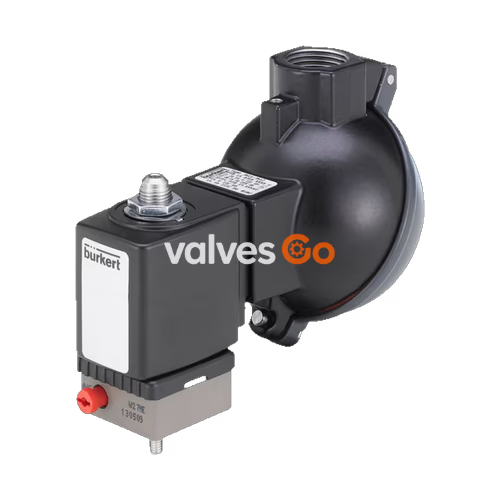
BURKERT 20071992 (Type 6014) is a direct-acting 3/2-way plunger solenoid valve configured for normally closed (Circuit Function C) operation with an integrated emergency manual override. The unit features an orifice diameter of 1.50 mm (1/16 inch), operating across a pressure range of 0.00 bar to 6.00 bar for both gaseous and liquid media. Constructed with a polyamide (PA) valve body designed for Bürkert 32 mm x 32 mm version A1 sub-base (SFB) mounting, it delivers a water flow factor Kv of 0.07 m³/h and an air flow rate QNn of 75 l/min.
Designed for hazardous environments, this configuration includes an encapsulated explosion-proof coil system certified under ATEX and IECEx directives (Ex mb IIC T5 Gb / Ex mb IIIC T95 °C Db). It is equipped with a factory-sealed 5,000 mm (5 m) polyolefin wire cable, rated for 24 V AC/DC (50/60 Hz), and certified for modular block mounting on multi-station pneumatic manifolds within ambient temperatures from -10 °C to +50 °C.
Type 6014 operates as a direct-acting plunger valve where the solenoid core acts directly on the valve seats without requiring pilot differential pressure. The stopper and the core guide tube are welded together to enhance internal pressure resistance and leak-tightness under continuous cycling. When de-energized, return spring force holds the lower plunger seal against inlet port 1 (P/NC), blocking flow, while outlet port 2 (A/OUT) remains vented through exhaust port 3 (R/NO). Upon electrical energization of the coil, the magnetic circuit draws the armature upward, opening the path from port 1 to port 2 and sealing exhaust port 3.
| Function Code | Description | De-energized State | Energized State |
|---|---|---|---|
| Circuit Function C (WW C) | 3/2-way valve, direct-acting | Inlet port 1 (P) closed; outlet port 2 (A) connected to exhaust 3 (R) | Inlet port 1 (P) connected to outlet port 2 (A); exhaust port 3 (R) closed |
Emergency Manual Override
The built-in manual override allows manual valve actuation during system setup, maintenance, or electrical interlock testing. The operator can mechanically displace the plunger to switch flow paths without energizing the coil. When operating via manual override, slight media leakage may occur depending on system pressure.
Valve 20071992 controls technical vacuum, neutral gases, and neutral fluids, including compressed air, town gas, natural gas, water, hydraulic oils, and petrol up to a maximum kinematic viscosity of 21 mm²/s. Switching performance measured at +20 °C and 6 bar at the valve outlet demonstrates an opening time between 10 ms and 15 ms (pressure increase 0% to 90%) and a closing time between 15 ms and 20 ms (pressure decrease 100% to 10%).
| Specification Parameter | Value / Range |
|---|---|
| Resource Article Number | 20071992 |
| Model Family | Type 6014 |
| Valve Construction | Complete valve |
| Nominal Orifice | 1.5 mm (1/16") |
| Operating Pressure (Gases / Liquids) | 0.00 bar to 6.00 bar (gauge) |
| Flow Coefficient Kv (Water) | 0.07 m³/h |
| Flow Coefficient QNn (Air) | 75 l/min |
| Nominal Operating Voltage | 24 V UC (AC: 50/60 Hz / DC) |
| Nominal Power Rating (SFB Block Mounting) | 7 W |
| Medium Temperature Range | -10 °C to +90 °C |
| Ambient Temperature Range | -10 °C to +50 °C (T5 rating) |
| Maximum Fluid Viscosity | 21 mm²/s |
| Switching Times (at 6 bar, +20 °C) | Opening: 10 ms to 15 ms; Closing: 15 ms to 20 ms |
| Degree of Protection | IP65 |
| Mounting Orientation | Unrestricted; actuator upright orientation recommended |
Permissible Pressures in Alternate Circuit Functions
Type 6014 valves use springs matched to specific functions. If reconfigured into alternative configurations, the maximum permissible operating pressure changes according to internal balance. For DN 1.5 units built with Function C springs, the maximum allowable pressures are: Function A: 16 bar; Function B: 22 bar; Function C: 16 bar; Function D: 2 bar; Function T: 2 bar.
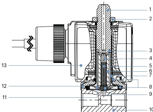
The media-wetted components of Burkert 20071992 combine high-grade technical polymers and corrosion-resistant stainless steels. The valve body is molded from polyamide (PA), providing mechanical stability while isolating the fluid path. The core guide assembly uses stainless steel grades 1.4105, 1.4303, and 1.4310 to ensure corrosion resistance against neutral industrial liquids and gases.
| Item | Component | Material |
|---|---|---|
| 1 | Stopper | Stainless steel 1.4105 / AISI 430F |
| 2 | Nut | Steel, thick-film passivated (brass body) / Stainless steel 1.4305 PTFE coated |
| 3 | Shading Ring | Copper (brass variant) / Silver (stainless steel variant) |
| 4 | Plunger Seal | FKM (Fluor rubber) |
| 5 | Springs | Stainless steel 1.4310 / AISI 301 |
| 6 | Magnetic Core (Armature) | Stainless steel 1.4105 / AISI 430F |
| 7 | Core Guide Tube | Stainless steel 1.4303 / AISI 305 / 308 |
| 8 | O-Rings | FKM (Fluor rubber) |
| 9 | Lower Plunger Seal | FKM (Fluor rubber) |
| 10 | Valve Body | Polyamide PA (Sub-base SFB variant) |
| 11 | Fastening Screws | Brass / Stainless steel 1.4301 / AISI 304 |
| 12 | Sub-Base Plate | Steel, thick-film passivated / Stainless steel 1.4301 / AISI 304 |
| 13 | Encapsulated Coil Body | Epoxy encapsulation |
Burkert 20071992 is engineered for operation in explosive atmospheres categorized under ATEX and IECEx standards. The coil features encapsulated Ex "m" construction, sealing electrical elements against combustible dust and gas ingress. The unit is certified under EU-Type Examination Certificate EPS 18 ATEX 1232 X and IECEx EPS 18.0110 X.
Electrical Wire Configuration (3-core, halogen-free polyolefin cable): • Green-Yellow Wire: Protective Conductor (PE / Earth Ground) • Black Wire 1: Neutral Conductor / Cathode (-) • Black Wire 2: Phase / Anode (+)
Temperature Class and Safety Rules
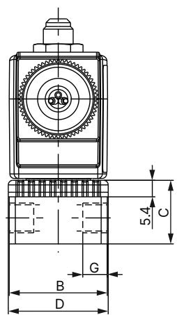
The valve utilizes the standardized Bürkert sub-base flange interface (SFB version A1), measuring 32 mm x 32 mm with a base depth of 14.3 mm and overall body length of 32.6 mm. The coil width (dimension E) measures 32 mm, and coil length (dimension F) is 46 mm for coil size 5.
| Interface Type | Body Dimension B [mm] | Base Height C [mm] | Body Length D [mm] | Coil Width E [mm] | Coil Length F [mm] |
|---|---|---|---|---|---|
| Sub-base Flange (SFB) | 32 | 14.3 | 32.6 | 32 | 46 |
Manifold Block Mounting Guidelines
When installing multiple valves on modular manifold blocks, adhere to the following installation specifications:
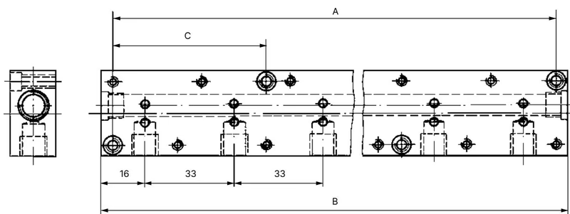
Burkert provides modular aluminum manifolds, connector nipples, and blanking plates to assemble compact valve clusters using SFB flange-mounted units.
| Accessory Description | Valve Positions | Hole Spacing A [mm] | Total Length B [mm] | Hole Spacing C [mm] | Article Number |
|---|---|---|---|---|---|
| Multiple Manifold (Aluminium) | 2 | 57 | 65 | — | 005023 |
| Multiple Manifold (Aluminium) | 3 | 90 | 98 | — | 005286 |
| Multiple Manifold (Aluminium) | 4 | 123 | 131 | — | 005287 |
| Multiple Manifold (Aluminium) | 5 | 156 | 164 | 57 | 005035 |
| Multiple Manifold (Aluminium) | 6 | 189 | 197 | 57 | 005038 |
| Multiple Manifold (Aluminium) | 8 | 255 | 263 | 90 | 005386 |
| Multiple Manifold (Aluminium) | 10 | 321 | 329 | 90 | 005764 |
| Single Manifold (Aluminium) | 1 | — | — | — | 005020 |
| Plug Nipple with O-Rings | — | — | — | — | 005040 |
| Covering Plate Kit (with screws & O-ring) | — | — | — | — | 005630 |
Explore similar products in our catalog


