

PN16

Burkert 20078061 Type 8647 AirLINE SP 28-bank electropneumatic valve island for Siemens ET 200SP/SP HA with 28x 2x3/2 NC valves (56 functions), D6 ports, P-HotSwap, and check valves.
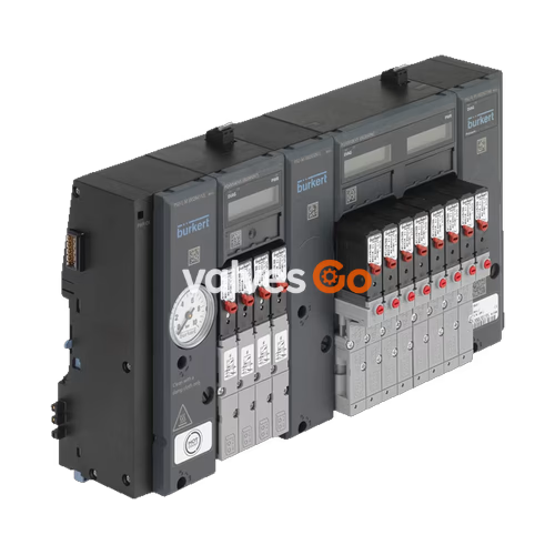
BURKERT 20078061 (Type 8647 AirLINE SP) is a modular electropneumatic valve island configured with a 28-bank pneumatic base for direct integration into Siemens SIMATIC ET 200SP and ET 200SP HA distributed I/O systems. Equipped with 28 stations of Type 6524 dual 3/2-way pilot solenoid valves, the unit provides 56 independently operated, normally closed (Circuit Function C C) pneumatic control channels within an 11 mm grid. It features integrated check valves in the exhaust channels, a pneumatic HotSwap function in pressure supply channel 1 (P), push-in D6 working ports located at the bottom of the pneumatic module, and a dedicated intermediate air supply feed module.
Article 20078061 belongs to the Type 8647 Revision 2 (REV.2) generation. REV.2 introduces an updated pneumatic base module architecture and standardized valve mounting interfaces compared to earlier configurations:
Each of the 28 stations houses a Type 6524 dual 3/2-way solenoid valve. Each valve assembly incorporates two separate flipper pilot mechanisms (Type 6144) driving pneumatic seat valve amplifiers, enabling fast response times and low energy consumption.

| Parameter | Specification |
|---|---|
| Operating Pressure Range | 2.5 bar to 10.0 bar (gauge pressure) |
| Standard Air Flow Rate ($Q_{Nn}$) | 300 l/min (measured at +20 °C, 6 bar inlet, 1 bar $\Delta p$) |
| Air Flow Rate with Integrated P-Shutoff | Approx. 240 l/min (reduced by ~20%) |
| Medium Temperature Range | 0 °C to +50 °C |
| Medium Quality | Filtered compressed air (dry, oiled or unoiled) per ISO 8573-1:2010 Class 7.4.4; 5 µm filtration |
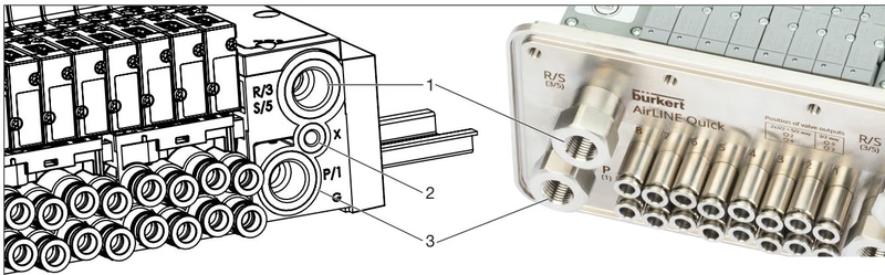
| Supply Port 1 (P) | G 1/4 female thread |
| Exhaust Ports 3 (R), 5 (S) | G 1/4 female thread with integrated non-return check valves (RSV) |
| Auxiliary / Pilot Exhaust (X) | M5 female thread |
| Working Ports 2 (A), 4 (B) | D6 (∅6 mm push-in coupling), bottom exit |
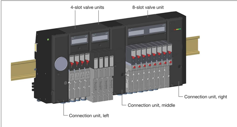
| Intermediate Supply Units | 1 PCE (PSU-M G 1/4) installed within the valve bank |
Intermediate Air Supply Requirement
In Type 8647 valve islands using Type 6524 dual 3/2-way valves, an intermediate feed unit (PSU-M) is required after every 16 valve functions to prevent internal pressure drops across large blocks. Article 20078061 incorporates 56 valve functions and includes 1 intermediate supply unit to ensure uniform pressure across all pneumatic stations.
The pneumatic base modules integrate non-return check valves (RSV) into the common exhaust lines 3 (R) and 5 (S). These check valves prevent pressure surges in the exhaust duct from triggering unintended movement in single-acting actuators during rapid venting.
The supply channel 1 (P) is equipped with a mechanical HotSwap shut-off valve. When a valve is removed from its station for servicing, the P channel automatically seals against supply pressure, leaving adjacent stations fully operational.
Depressurization on Valve Removal
While the integrated P shut-off stops supply pressure, removing a valve immediately vents remaining pressure in working ports 2 (A) and 4 (B). Connected actuators will depressurize and may change position. Always secure actuators mechanically before dismounting valves.
Type 8647 mounts directly on the standard DIN rail adjacent to Siemens SIMATIC ET 200SP or ET 200SP HA distributed I/O modules, establishing electrical and backplane communication without external wiring.

| Software Environment | Configuration Tool | Integration Details |
|---|---|---|
| Siemens TIA Portal | HSP0225 (V14 SP1 or higher) / GSDML | Hardware Support Package enables drag-and-drop module setup and automatic rule checking |
| Siemens STEP 7 Classic | HSP2105 (V5.5 SP4 or higher) / GSD | Full integration via Hardware Support Package or device master file |
| Siemens PCS 7 | HUP (V9.0 SP2 or higher) | Hardware Update Package supports integration with PCS 7 process control systems |
| Third-Party Fieldbus Masters | GSD (PROFIBUS) / GSDML (PROFINET) | Universal integration via standard device description files |
Each electronic base module (PQ module) provides local switching electronics, internal protection, and status displays for its assigned valve slots.
On Type 6524 dual 3/2-way valve modules, both working connections are active:
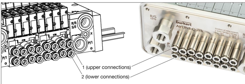
Tubing Preparation Guidelines (ISO 14743:2020)
Cut pneumatic tubing precisely at a 90° angle without burrs. Outer diameter tolerance for 6 mm tubing must not exceed ±0.08 mm for polyamide (PA) or ±0.10 mm for polyurethane (PU). Insert tubing firmly until the internal grip ring engages. Minimum pull-off retention force is 120 N for PA and 100 N for PU.
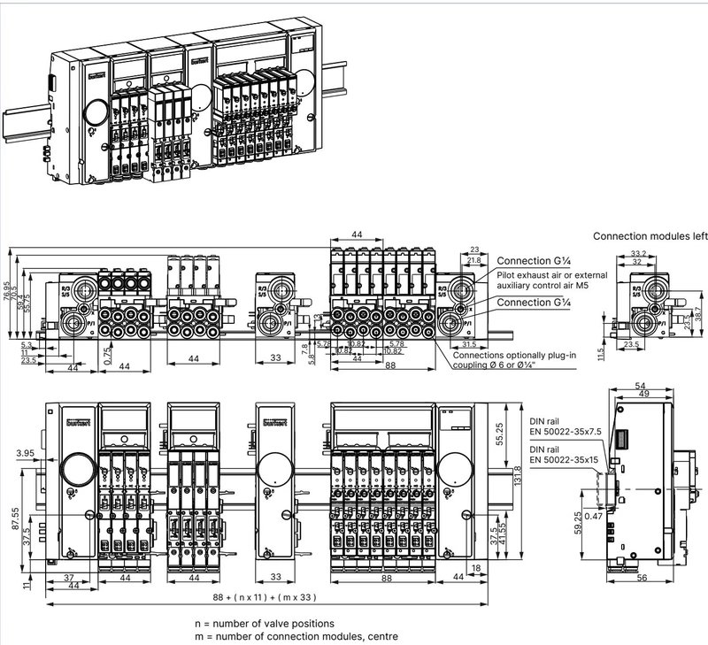
| Component Description | Package Content | Article Number |
|---|---|---|
| Replacement Valve Type 6524 2x3/2-way NC (2.5 to 10 bar, 24 V DC, REV.2) | 1 piece | 204710 |
| Replacement Valve Type 6524 2x3/2-way NC without manual override | 1 piece | 300818 |
| Valve Seal Set FM20 for Type 6524 2x3/2-way | 12 seals | 20016305 |
| Module Seal Set MP16 for REV.2 base modules | 4 seals | 20024339 |
| Intermediate Feed Unit G 1/4 (PSU-M, 11 mm) | 1 piece | 20030063 |
| Left Connection Unit G 1/4 (PSU-L, 11 mm) | 1 piece | 20030062 |
| Right Connection Unit G 1/4 (PSU-R, 11 mm) | 1 piece | 20030064 |
| Pneumatic Base Module 4-slot, D6, FM20, HotSwap, RSV | 1 piece | 20040335 |
| Electronic Base Module PQ8VS4 (4-slot, double valve) | 1 piece | 20040550 |
| Electronic Base Module PQ16VS8 (8-slot, double valve) | 1 piece | 20040556 |
| Cover Plate for Type 6524 2x3/2-way unused slots (REV.2) | 1 piece | 661092 |
| Electrical Connection Cover (all valve types) | 1 piece | 653670 |
| Push-in Connector ∅6 mm Brass | 8 pieces | 20024340 |
| Push-in Connector ∅6 mm Stainless Steel (VA) | 8 pieces | 20024341 |
Explore similar products in our catalog


