

PN16

BURKERT 20079259 Type 8647 AirLINE SP pneumatic valve island features 28-bank 5/2-way valves, 11 mm width, G 1/4 supply, D6 ports, 2.5–10 bar range, and direct Siemens ET 200SP / ET 200SP HA integration.
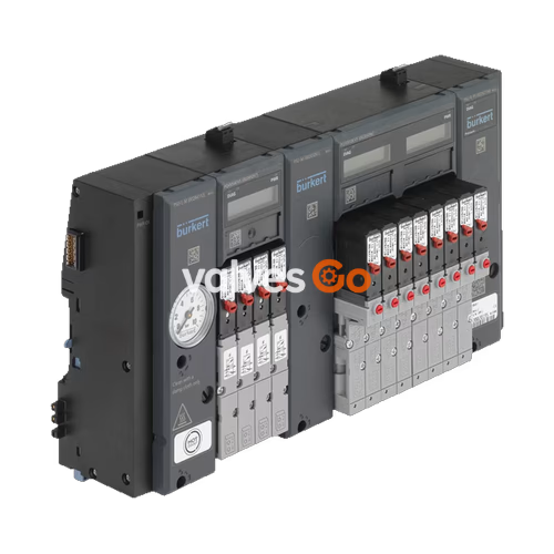
BURKERT 20079259 (Type 8647 AirLINE SP) is a modular electropneumatic automation system factory-configured as a 28-bank valve island. The system integrates 28 monostable 5/2-way pilot valves (Circuit Function H) with an 11 mm station width onto modular pneumatic base sub-bases. Primary compressed air supply and dual exhaust ports are sized at G 1/4, while working connections 2 (A) and 4 (B) are routed through D6 mm push-in couplings on the bottom face of each pneumatic base module. The assembly is built to hardware Generation Revision 2 (REV.2), featuring standardized FM20 fluidic flange profiles and wavy working port tube connector arrangements.
Type 8647 interfaces directly with Siemens distributed I/O systems SIMATIC ET 200SP and SIMATIC ET 200SP HA via the backplane bus, enabling unified engineering within Siemens STEP 7 Classic, TIA Portal, or PCS 7 environments. Because the 28-bank layout exceeds 24 valve functions, this assembly includes one factory-installed intermediate feed unit (PSU-M, 33 mm width) to maintain uniform pressure across all pneumatic stations without line-starvation during concurrent switching.
| Product Property | Technical Specification |
|---|---|
| Model / SKU | 20079259 |
| System Type / Revision | Type 8647 / Revision 2 (REV.2) |
| Number of Valve Slots / Functions | 28 valve slots / 28× 5/2-way valve function H (CF H) |
| Width per Station | 11 mm |
| Intermediate Air Feed | 1 PCE (PSU-M, 33 mm width, G 1/4) |
| Pressure Range | 2.5 bar to 10.0 bar (gauge overpressure) |
| Nominal Flow Rate $Q_{\text{Nn}}$ (Air) | 300 l/min (measured at +20 °C, 6 bar inlet, 1 bar $\Delta p$) |
| Operating Medium | Dry compressed air, lubricated or unlubricated; neutral gases |
| Compressed Air Quality | ISO 8573-1:2010, Class 7.4.4 (5 µm filtration recommended) |
| Medium Temperature | 0 °C to +50 °C |
| Ambient Temperature | 0 °C to +55 °C |
| Operating Voltage | 24 V DC (±10%, SELV/PELV, residual ripple 2.4 Vss) |
| Nominal Power per Valve | 0.8 W (Type 6525 pilot valve) |
| Nominal Current per Valve | 40 mA inrush, 28 mA holding current after 120 ms |
| Operating Duty Cycle | 100% continuous operation (100% ED) |
| Degree of Protection | IP20 (verified by Bürkert; IP65 in closed control cabinet) |
| Protection Class | III according to DIN EN 61140, VDE 0140 |
| Installation Mounting | DIN rail mounting in industrial control cabinets |
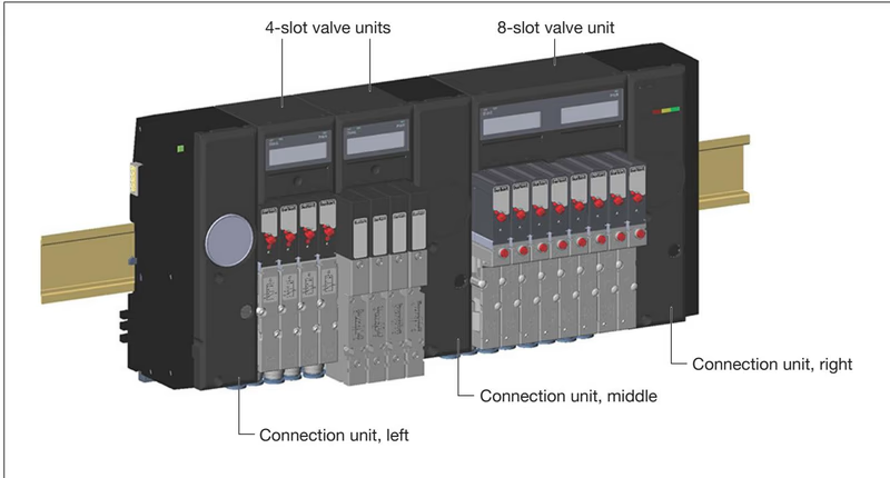
Type 8647 AirLINE SP combines connection units, pneumatic base modules, electronic base modules (PQ modules), and pilot valves into a unified electro-pneumatic block.
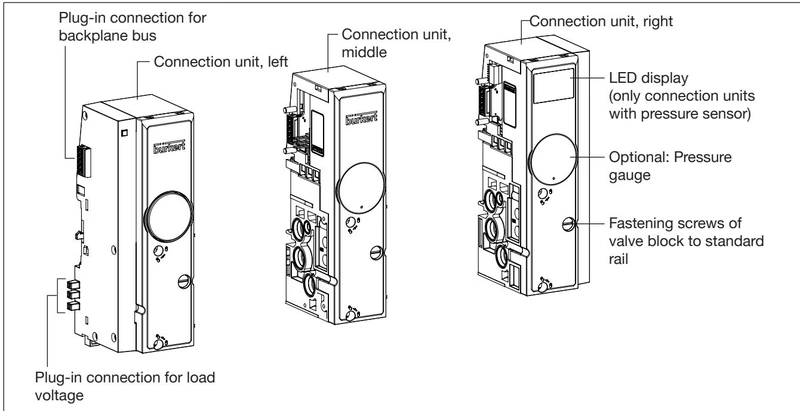
Pneumatic supply, exhaust ventilation, and mechanical DIN rail anchoring are handled by connection units located at the left, center, and right of the valve island:
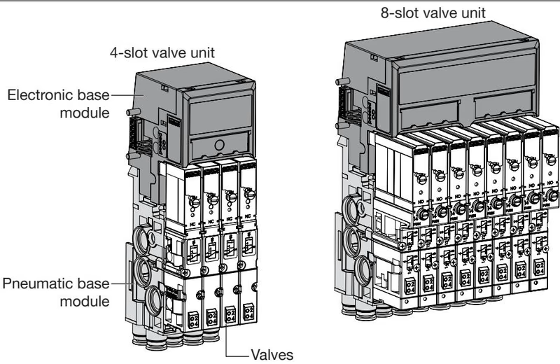
Each valve unit consists of three interlocking sub-assemblies:
BURKERT 20079259 is manufactured to the Revision 2 (REV.2) build standard. Revision 2 incorporates specific physical and pneumatic enhancements compared to first-generation REV.1 equipment:
| Distinguishing Feature | Revision 1 (REV.1) | Revision 2 (REV.2) |
|---|---|---|
| Hose Release Ring Color | Black | Blue |
| Working Connection Port Layout | Parallel linear array | Wavy staggered layout |
| Single Valve Pneumatic Flange | FM14 flange profile | Standardized FM20 flange profile |
| Type Label Designation | No revision marking | Explicit "Rev.2" inscription |
| Flow Reduction with P-Shut-off | Up to 50% flow reduction | Max. 20% flow reduction |
Flange Interface Compatibility
Single valves with FM14 flange (REV.1) and FM20 flange (REV.2) are mechanically incompatible and cannot be interchanged. When replacing 5/2-way valves on 20079259, select REV.2 valves with FM20 flange patterns (such as Article 20029920 or 20029925).
Type 8647 communicates through the backplane bus of the Siemens SIMATIC ET 200SP / ET 200SP HA distributed I/O station. The valve block latches mechanically and electrically directly to the Siemens BaseUnits on the standard mounting rail.
| Engineering Tool | Configuration File / Method | ET 200SP Compatibility | ET 200SP HA Compatibility |
|---|---|---|---|
| Any Fieldbus Tool | GSD (PROFIBUS DP) / GSDML (PROFINET IO) | Compatible | Compatible (GSDML only) |
| SIMATIC STEP 7 Classic | HSP2105 (V5.5 SP4 or higher) | Compatible | Not Supported |
| SIMATIC TIA Portal | HSP0225 (V14 SP1 or higher) | Compatible | Not Supported |
| SIMATIC PCS 7 | HUP package (V9.0 SP2 or higher) | Compatible (requires HF IM) | Compatible |
Type 8647 provides three distinct electrical shutdown methods for safety applications:
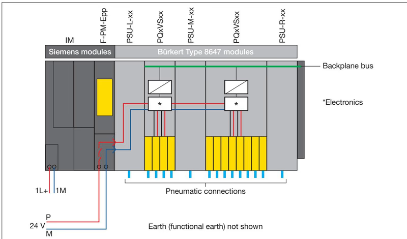
Manual Override Safety Precaution
Manual overrides mechanically bypass any electrical safety shutdown. For safety-critical circuits, either select replacement valves without manual override (Article 20029925) or install lockouts to prevent accidental manual operation.
Each electronic base module (PQ module) provides a graphical liquid crystal display and local LEDs to indicate operating conditions:
Wire Break Ch. x, Short Circuit Ch. x, EVS active, PROFIenergy active, and Pilot SCC Limit Ch. x.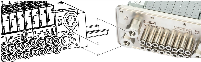
Mount the valve block horizontally or vertically on a standard DIN rail anchored firmly inside a minimum IP54 enclosure. Ensure a minimum clearance of ≥ 5 cm between the upper edge of the valve block and the cabinet ceiling (≥ 8 cm when EVS connectors are utilized) to permit heat dissipation and allow screwdriver access.
| Connection Port | Marking / Function | Recommended Torque | Maximum Permissible Torque |
|---|---|---|---|
| G 1/4 | Supply P/1, Exhaust R/3, S/5 | 4 to 7 Nm | 20 Nm |
| M5 | Auxiliary control air / pilot exhaust | 1.0 to 1.2 Nm | 3 Nm |
| M2 Screws | Valve fastening screws | 0.25 to 0.30 Nm | 0.35 Nm |
| Rail Screws | Standard rail clamping screws | approx. 1.8 Nm | 2.0 Nm |
To prevent leakage or tube release in push-in connections:
Compressed Air Line Assignment
Never interchange supply port 1 (P) and exhaust ports 3/5 (R/S). Exhaust connections must never be blocked or plugged. Insufficient exhaust venting creates backpressure that can cause unwanted switching or sluggish actuator reaction.
| Position / Component | Description | Content | Article No. |
|---|---|---|---|
| Replacement Valve Type 6525 | 5/2-way CF H, REV.2, FM20 flange, 24 V DC, with manual override | 1 piece | 20029920 |
| Replacement Valve Type 6525 | 5/2-way CF H, REV.2, FM20 flange, 24 V DC, without manual override | 1 piece | 20029925 |
| Intermediate Supply Unit | PSU-M intermediate feed, 11 mm width, G 1/4 | 1 piece | 20030063 |
| Pneumatic Base Unit | 4-fold base module, 11 mm station width, D6 push-in, FM20 | 1 piece | 20040334 |
| Cover Plate | Cover plate for unused valve slots, Type 6524/6525 REV.2 | 1 piece | 661092 |
| Electrical Cover | Cover for unused electrical plug connections | 1 piece | 653670 |
| Valve Seal Kit | Replacement profile seals FM20 for Type 6524/6525 REV.2 | 12 pieces | 20016305 |
| Module Seal Kit | Replacement intermediate module seals MP16 | 4 pieces | 20024339 |
| Tube Support Sleeve | Support sleeve for flexible D6 PU tubing in push-in fittings | - | 20099400 |
Explore similar products in our catalog


